Energy storage device for electric operating mechanism

A technology of electric operating mechanism and energy storage device, which is applied to the power device inside the switch, etc., to achieve the effect of saving time and effort, saving cost and strong applicability of installation.

Active Publication Date: 2015-07-08
WUXI KAIXUAN MOTOR +1
View PDF8 Cites 0 Cited by
  • Summary
  • Abstract
  • Description
  • Claims
  • Application Information

AI Technical Summary

Problems solved by technology

[0004] The object of the present invention is to provide an energy storage device for an electric operating mechanism, which has the characteristics of small size, convenient installation, wide application range and large energy storage in a relative volume, so as to solve the problem of existing electric operating mechanisms in the prior art. The problem

Method used


Image

  • Energy storage device for electric operating mechanism
  • Energy storage device for electric operating mechanism
  • Energy storage device for electric operating mechanism

Examples


Embodiment 1

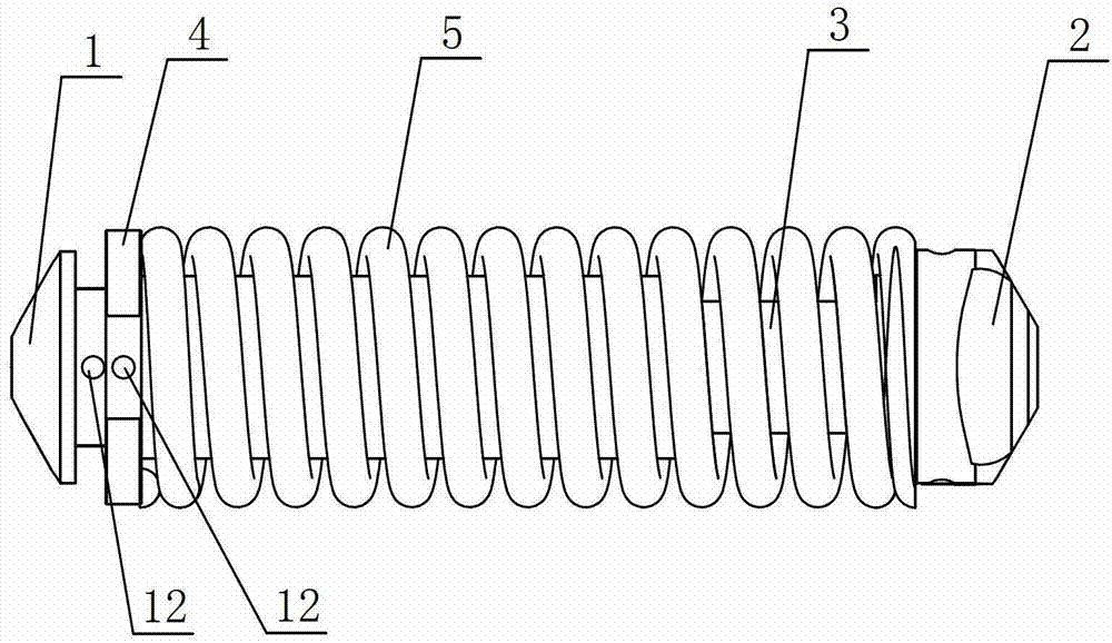
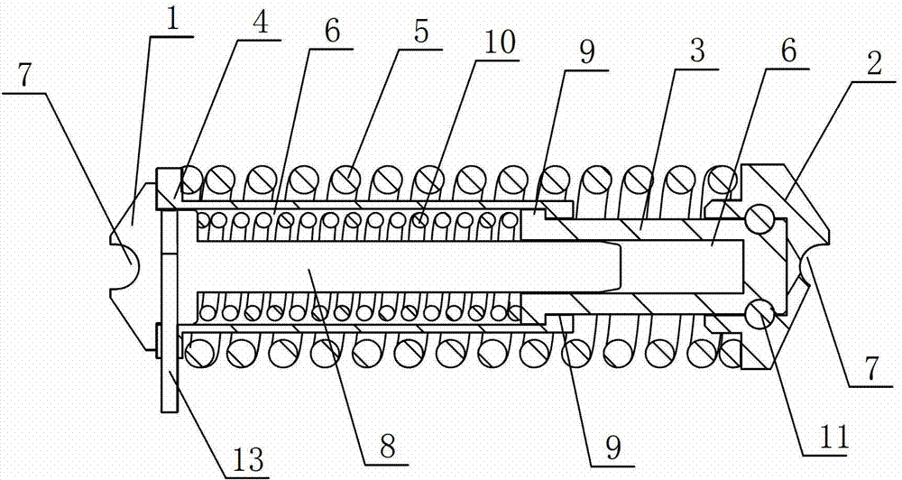
[0024] see figure 1 and figure 2 As shown, in this embodiment, an energy storage device for an electric operating mechanism includes a first collet 1, a second collet 2, an inner mounting sleeve 3, an outer mounting sleeve 4, an outer energy storage spring 5 and The inner energy storage spring 10, the outer ends of the first collet 1 and the second collet 2 are opened to facilitate fixing the entire energy storage device on the electric operating mechanism and run through the arc-shaped installation groove 7 of the entire collet, Both the inner mounting sleeve 3 and the outer mounting sleeve 4 have an accommodating cavity 6 for accommodating an energy storage spring, and an outer energy storage spring 5 is arranged between the outer mounting sleeve 4 and the second collet 2, after assembly One end of the outer energy storage spring 5 abuts against the inner wall of the second collet 2, and the other end abuts against the inner wall of the outer mounting sleeve 4, and the fir...

Embodiment 2

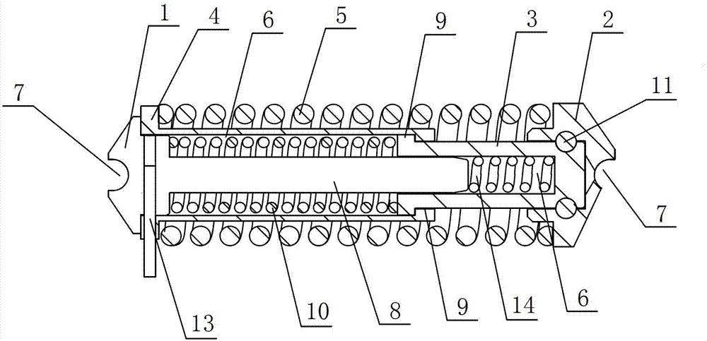
[0030] see figure 1 and image 3 As shown, this embodiment is based on the first embodiment, and when the accommodating cavity 6 of the inner mounting sleeve 3 has a sufficiently large stroke, an auxiliary energy storage spring is arranged in the accommodating cavity 6 of the inner mounting sleeve 3 14. One end of the auxiliary energy storage spring 14 abuts against the bottom of the accommodating chamber 6 of the inner mounting sleeve 3, and the other end abuts against the end of the guide rod 8, and relies on the outer energy storage spring 5 and the inner energy storage spring when storing energy. 10 and the auxiliary energy storage spring 14 are compressed simultaneously to store energy, so as to further reduce the volume of the entire energy storage device.

[0031] When working, the electric operating mechanism compresses the outer energy storage spring 5 and the inner energy storage spring 10 by compressing the installation slots 7 at both ends of the first collet 1 an...


PUM


Abstract

The invention discloses an energy storage device for an electric operating mechanism. The energy storage device comprises a first spring chuck, a second spring chuck and a spring energy storage component which is arranged between the two spring chucks, wherein the spring energy storage component comprises an inner mounting sleeve and an outer mounting sleeve; the inner and outer mounting sleeves are provided with containing cavities capable of containing energy storage springs; one end of the inner mounting sleeve penetrates through the containing cavity of the outer mounting sleeve and is fixedly connected with the second spring chuck; the other end of the inner mounting sleeve is connected with the outer mounting sleeve through steps which are arranged corresponding to the inner and outer mounting sleeves; an outer energy storage spring is arranged between the outer mounting sleeve and the second spring chuck; an inner energy storage spring is arranged in the containing cavity of the outer mounting sleeve; and the outer ends of the first and second spring chucks are provided with mounting grooves. The energy storage device has the advantages that the device is simply mounted in a time-saving and labor-saving mode, the volume of the whole energy storage device can be effectively reduced, and the miniaturization development requirements of circuit breakers are met; and moreover, stored energy of the springs is increased in relative volume, contacts of the circuit breakers are effectively protected, and the cost is saved.

Description

technical field [0001] The invention relates to a spring energy storage device, in particular to an energy storage device for an electric operating mechanism. Background technique [0002] As we all know, springs are widely used in various mechanical equipment as important mechanical parts. Their main function is to generate elastic deformation under the action of external force, store energy, and release energy quickly when needed to meet the designer's use requirements. Most of the existing electric operating mechanisms do not have a spring energy storage mechanism. The opening and closing actions of the circuit breaker are realized by the direct rotation of the motor in the electric operating mechanism, but the opening and closing speed of the circuit breaker is unqualified, such as just opening or closing. If the just closing speed is too low, the arcing time will be prolonged, and the high temperature of the arc will cause the arc extinguishing medium to be carbonized o...

Claims


Application Information

Patent Timeline
Patent Type & Authority Patents(China)
IPC IPC(8): H01H3/30
Inventor 汪永峰
Owner WUXI KAIXUAN MOTOR
Why Eureka
Try Eureka