
An adjustable stent for digestive endoscopy

A digestive endoscope and adjustable technology, which can be used in saliva-receiving instruments, stereotaxic surgical instruments, irradiation and other directions. , the effect of preventing movement

Inactive Publication Date: 2019-01-08
袁海锋
View PDF6 Cites 2 Cited by
  • Summary
  • Abstract
  • Description
  • Claims
  • Application Information

AI Technical Summary

Problems solved by technology

[0002] Digestive endoscopy is a method of medical examination, and it also refers to the equipment used in this examination. Digestive endoscopy can directly observe the real situation of the inspected part, and can also conduct pathological biopsy and cytological examination on suspicious lesions. To further confirm the diagnosis, it is the preferred examination method for upper gastrointestinal lesions. It uses a thin and flexible tube to extend into the stomach. Doctors can directly observe the lesions of the esophagus, stomach and duodenum, especially for small lesions. Therefore, There is an increasing demand for adjustable digestive endoscope brackets. When the transmission digestive endoscope is in use, the patient may turn his head, and the digestive endoscope may cause damage to the patient's digestive tract. Doctors need to hold the light guide all the time. The operation is more troublesome, and at the same time, the outer surface of the guide beam will be contaminated with bacteria in the air, which will be brought into the patient's body and cause esophageal infection. When the digestive endoscope passes through the patient's throat, the patient may vomit

Method used

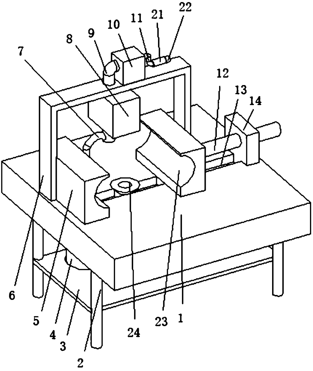

Image

  • An adjustable stent for digestive endoscopy
  • An adjustable stent for digestive endoscopy
  • An adjustable stent for digestive endoscopy

Examples


Embodiment Construction

[0014] The following will clearly and completely describe the technical solutions in the embodiments of the present invention with reference to the accompanying drawings in the embodiments of the present invention. Obviously, the described embodiments are only some, not all, embodiments of the present invention. Based on the embodiments of the present invention, all other embodiments obtained by persons of ordinary skill in the art without making creative efforts belong to the protection scope of the present invention.

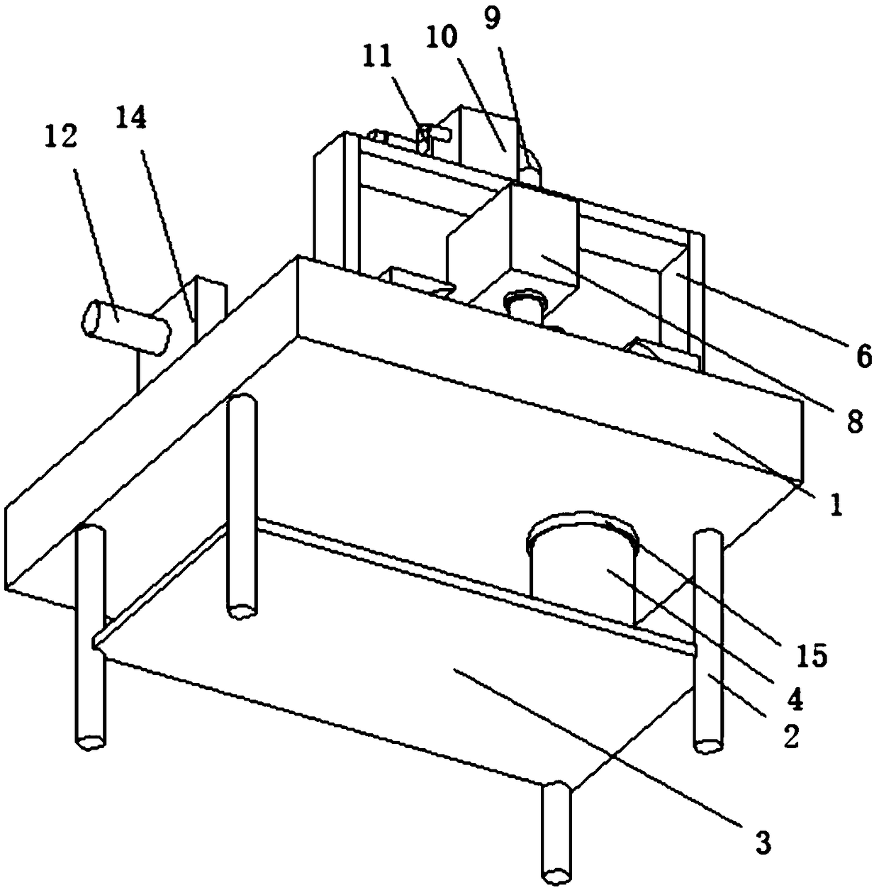
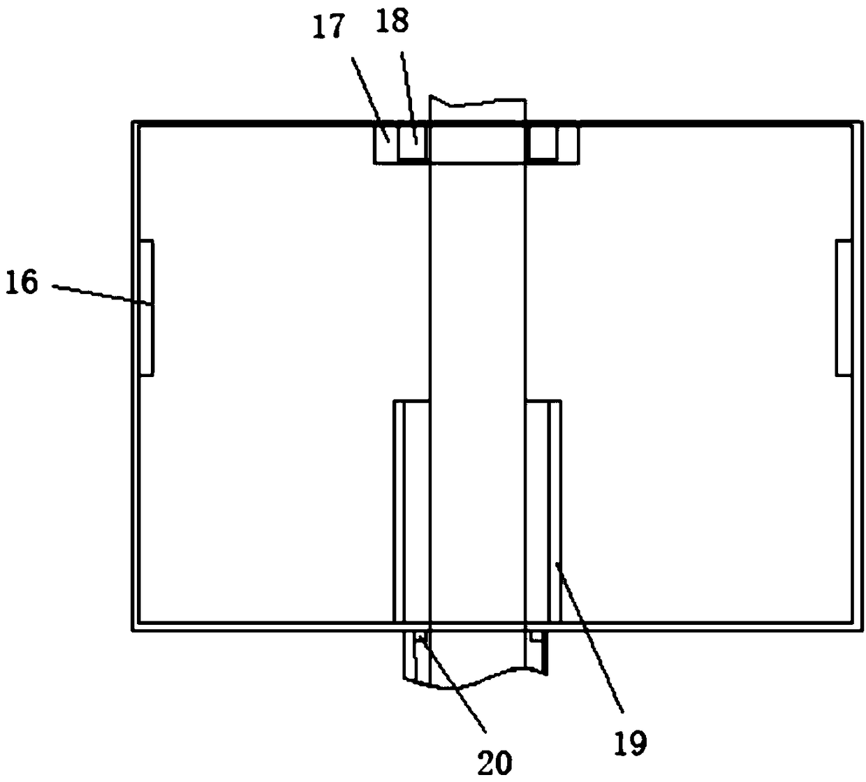
[0015] see Figure 1-3 , the present invention provides a technical solution: an adjustable digestive endoscope bracket, including a base 1, a U-shaped bracket 6 is arranged on the left end of the upper surface of the base 1, and the left end of the U-shaped bracket 6 is located at the left end of the upper surface of the base 1 Be provided with fixed stopper 5, fixed stopper 5 limits head to move to the right, be positioned at fixed stopper 5 right side and b...


PUM


Abstract

The invention discloses an adjustable digestive endoscopic stent including a base. The left end of the upper surface of the base is provided with a U-shaped bracket. A left end of that U-shape bracketis provided with a fixed limit block at the left end of the upper surface of the chassis. A slide groove is arranged on the upper surface of the base on the right side of the fixed stopper. At that right end of the slide groove, a fixing plate is arranged on the upper surface of the base. A sliding limit block is slidably connected with the sliding groove. The sliding stopper is inside the U-shaped bracket. The right side of the sliding limiting block is provided with a stud. An end of the stud remote from the sliding limit block passes through a threaded hole in the fixing plate and extendsto the outside. A light guide disinfection box is arranged on that inn top side of the U-shaped bracket, which can fix the patient's head, prevent digestive endoscope from causing injury to the digestive tract of the patient and trouble to the doctor in operation, sterilize the outer surface of the light guide, avoid esophageal infection caused by carrying the light guide into the patient, and collect vomitus of the patient, wherein the light guiding disinfection box is arranged on the outer surface of the U-shaped bracket.

Description

technical field [0001] The invention relates to the technical field of digestive endoscope stabilization, in particular to an adjustable digestive endoscope bracket. Background technique [0002] Digestive endoscopy is a method of medical examination, and it also refers to the equipment used in this examination. Digestive endoscopy can directly observe the real situation of the inspected part, and can also conduct pathological biopsy and cytological examination on suspicious lesions. To further confirm the diagnosis, it is the preferred examination method for upper gastrointestinal lesions. It uses a thin and flexible tube to extend into the stomach. Doctors can directly observe the lesions of the esophagus, stomach and duodenum, especially for small lesions. Therefore, There is an increasing demand for adjustable digestive endoscope brackets. When the transmission digestive endoscope is in use, the patient may turn his head, and the digestive endoscope may cause damage to t...

Claims


Application Information

Patent Timeline
IPC IPC(8): A61B90/14A61J19/00A61L2/10
CPCA61J19/00A61L2/10A61B90/14
Inventor 袁海锋付景
Owner 袁海锋
Learn More