
Hydraulic force-controllable and angle-adjustable tooth extraction device

A technology of angle and force, applied in the field of hydraulic tooth extraction device, can solve the problems of difficult control of tooth extraction force and laborious operation, and achieve the effect of reducing damage

Pending Publication Date: 2019-01-08
张珈源
View PDF0 Cites 4 Cited by
  • Summary
  • Abstract
  • Description
  • Claims
  • Application Information

AI Technical Summary

Problems solved by technology

[0005] In dental surgery, it is often necessary to pull out bad teeth. The tooth extraction forceps currently used rely entirely on the strength of the doctor's arm to pull out the bad teeth bluntly. The force of tooth extraction is difficult to control and the operation is laborious.

Method used


Image

  • Hydraulic force-controllable and angle-adjustable tooth extraction device
  • Hydraulic force-controllable and angle-adjustable tooth extraction device
  • Hydraulic force-controllable and angle-adjustable tooth extraction device

Examples


Embodiment 1

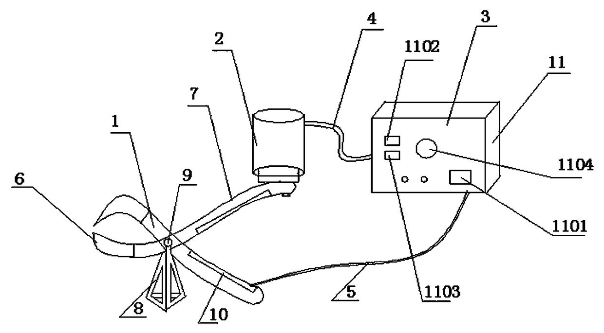
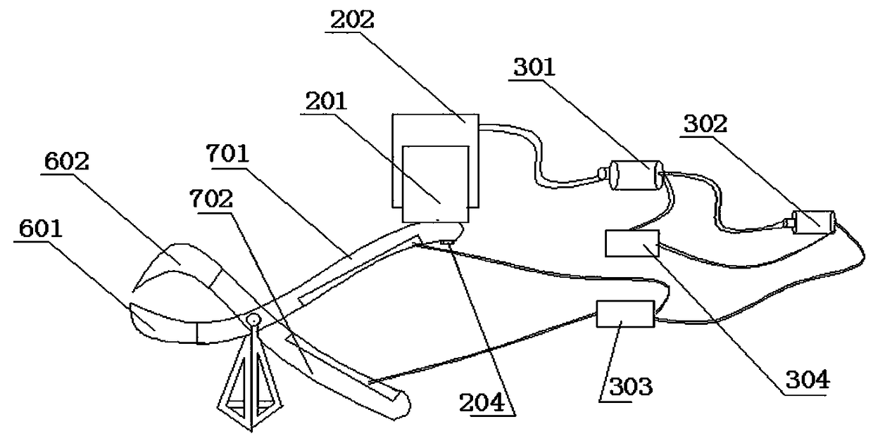
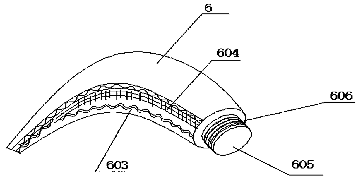
[0021] Such as figure 1 , figure 2 , image 3 , Figure 4 As shown, a hydraulic tooth extraction device with controllable force and adjustable angle includes a tooth extraction forceps 1, a hydraulic lifting device 2, a driving device 3 and an external power supply, and the tooth extraction forceps 1 is fixedly connected to the hydraulic lifting device 2 through a support rod 203 , the hydraulic lifting device 2 is connected to the driving device 3 through the oil pipe 4, and the driving device 3 is electrically connected to the tooth extraction forceps 1 through the wire 5, and the tooth extraction forceps 1 includes a jaw 6, a body 7, and a tripod 8 , the pliers mouth 6 includes a first pliers mouth 601 and a second pliers mouth 602, the inner surfaces of the first pliers mouth 601 and the second pliers mouth 602 are provided with wave-shaped grooves 603 and anti-slip lines 604, the wave-shaped The groove 603 and the anti-slip pattern 604 are used to fix the teeth and pr...

Embodiment 2

[0023] Such as figure 1 , figure 2 , image 3 , Figure 4 As shown, the first pliers mouth 601 and the second pliers mouth 602 can be used interchangeably, so that the tooth extraction angle can be adapted by replacing the first pliers mouth 601 and the second pliers mouth 602 due to the different angles of the upper teeth and lower teeth.

Embodiment 3

[0025] Such as figure 1 , figure 2 , Figure 4 As shown, the tripod bracket 8 is disassembled and connected to the rotating shaft, which is convenient for assembly and replacement.


PUM


Abstract

The invention discloses a hydraulic force-controllable and angle-adjustable tooth extraction device. The tooth extraction device comprises tooth extraction forceps, a hydraulic lifting device, a driving device and an external power supply; the tooth extraction forceps are fixedly connected with the hydraulic lifting device through a supporting rod; the hydraulic lifting device is connected with the driving device through an oil pipe; the driving device is electrically connected with the tooth extraction forceps through a lead; the tooth extraction forceps comprise jaws, bodies and a triangularsupport; the hydraulic lifting device comprises a piston, an oil cylinder block and the supporting rod; and the driving device comprises a casing, a hydraulic oil pump, a hydraulic oil pump motor, astorage battery and a controller. The tooth extraction fulcrum is arranged outside the mouth, so that the damage to the mouth is reduced; wave type grooves and protecting lines on the jaws can well fix a tooth to be extracted; manpower is replaced by hydraulic force application, so that the tooth extraction force is stable and controllable, and the extraction dimension can be limited during toothextraction; the tooth extraction angle can be adjusted according to the screwing depth of long screws on the jaws, and the force can be applied according to the tooth root direction, that is, the force application direction of the instrument is adjustable.

Description

technical field [0001] The invention relates to a dental instrument, in particular to a hydraulic tooth extractor with controllable force and adjustable angle. Background technique [0002] At present, in oral and dental medical treatment, it is one of the most helpless final treatment methods for doctors to finally extract the diseased teeth that cannot be treated further. Tooth extraction generally exists in the process of dental treatment. In oral clinical surgery, tooth extraction, Most of them use the principle of lever mechanics in physics to extract teeth with instruments, which usually include a variety of metal medical instruments such as tooth lifts, chisels, hammers, and tooth extraction forceps. Tooth extraction forceps are necessary medical devices for tooth extraction. When hospitals and dental clinics use existing tooth extraction forceps and other medical devices to extract teeth for patients, doctors need to pay a lot of effort to shake the teeth, and then s...

Claims


Application Information

Patent Timeline
IPC IPC(8): A61C3/14A61C1/02
CPCA61C1/02A61C3/14
Inventor 张珈源
Owner 张珈源
Learn More