Large vacuum pump impeller casting method

A technology for vacuum pumps and impellers, applied in casting molding equipment, molding boxes, casting molds, etc., which can solve the problems of large impeller mold volume, damage to molds and sand boxes, and large blades, so as to avoid casting size deviation and improve use Effect of improving life and strength

Active Publication Date: 2019-01-08
ZIBO WATER RING VACUUM PUMP FACTORY +2
View PDF7 Cites 4 Cited by
  • Summary
  • Abstract
  • Description
  • Claims
  • Application Information

AI Technical Summary

Problems solved by technology

When the sand box is separated from the mold, it needs to be lifted by a crane to separate the sand box from the mold. However, due to the large volume of the large impeller mold and the large number of blades, it is very difficult to remove the mold during molding. Currently, it is usually hammered when removing the mold. This method is easy to cause damage to the mold and the sand box, and the large impeller of the water ring vacuum pump is very difficult to mold due to its large volume and large number of blades during the casting production process.

Method used


Image

  • Large vacuum pump impeller casting method
  • Large vacuum pump impeller casting method
  • Large vacuum pump impeller casting method

Examples


Embodiment 1

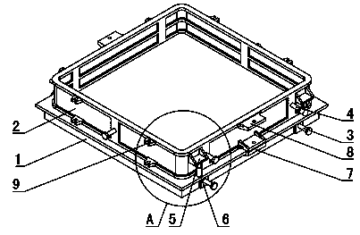
[0041] Such as Figure 1~2 Shown: the base 1 is a square plate arranged horizontally, the underside of the base 1 is provided with a base support tube, the base support tube is a square tube, the side length of the base support tube is smaller than the side length of the base 1, and the base support tube and the base 1 centerlines coincide.

[0042] The main body of the sand box 2 is a square cylinder with both upper and lower ends open. The side length of the main body of the sand box 2 is smaller than the side length of the base 1. The center line of the main body of the sand box 2 coincides with the center line of the base 1, and the One side is arranged parallel to the side corresponding to the base 1 . The main body of the flask 2 is provided with multiple layers from bottom to top, and in this embodiment, the main body of the flask 2 has one and only one layer.

[0043] In this embodiment, the front side and the rear side of the sand box main body 2 are all provided wi...

Embodiment 2

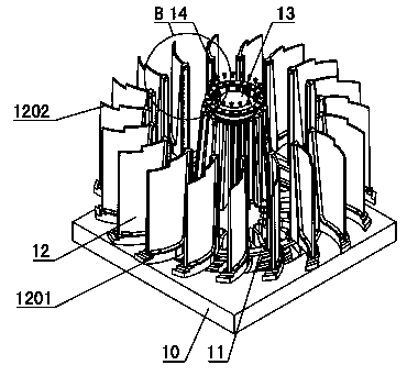
[0073] Such as Figure 7 As shown: the difference between Embodiment 2 and Embodiment 1 is that: the blade 12 and the column 13 are integrated, and the blade 12 and the column 13 are divided into three sections evenly, and the internal pressure ring 14 is not provided between the blade 12 and the column 13 . Adjacent blades 12 located at one end of the lowermost side are connected by ribs. In this embodiment, the main body 2 of the flask is also provided with three layers, that is, the number of layers of the main body 2 of the flask is equal to the number of segments of the impeller mold, which is convenient for demoulding of the impeller.

[0074]Seam-riding pins are arranged between the corresponding blades 12 of every adjacent two sections of blades 12, which reduces the stress deformation of the blades 12, prevents the mold from being squeezed and deformed during the molding process, and improves the strength of the mold.


PUM

PropertyMeasurementUnit
diameteraaaaaaaaaa

Abstract

The invention relates to a large vacuum pump impeller casting method and belongs to the technical field of production of a vacuum pump impeller. The large vacuum pump impeller casting method is characterized by comprising the following steps: 1) mounting a mold in a sand box; 2) filling a sand box main body (2) with molding sand, tamping, scraping the redundant molding sand, and arranging a casting head and a vent hole; 3) drawing the sand box main bodies (2) one by one from top to bottom, lifting the corresponding sand box main body (2) by a lifting device, lifting the sand box main body (2)through a travelling crane, and synchronously lifting by the lifting device corresponding to the same layer of sand box main body (2); 4) taking out the mold and sequentially performing mold closing on the sand box main body (2) through the travelling crane; and 5) fixedly connecting a pedestal (1) with the adjacent sand box main body (2) as well as each adjacent two layers of sand box main bodies(2). By the large vacuum pump impeller casting method, the operation of lifting the sand box main bodies by the travelling crane, rapidly lifting the mold and separating from the mold is facilitated.

Description

technical field [0001] The invention discloses a large vacuum pump impeller casting method, which belongs to the technical field of vacuum pump impeller production. Background technique [0002] The use of standard flasks for large impellers facilitates castings of high quality and low cost. When the sand box is separated from the mold, it needs to be lifted by a crane to separate the sand box from the mold. However, due to the large volume of the large impeller mold and the large number of blades, it is very difficult to remove the mold during molding. Currently, it is usually hammered when removing the mold. This way is easy to cause damage to the mold and the sand box, and in the casting production process of the large impeller of the water ring vacuum pump, due to its large volume and large number of blades, it is very difficult to mold during molding. Therefore, it is very important to develop a reasonable process and tooling for the production of impellers. Contents...

Claims


Application Information

Patent Timeline
Patent Type & Authority Applications(China)
IPC IPC(8): B22C21/02B22C9/02B22C9/22
CPCB22C9/02B22C9/22B22C21/02
Inventor 徐红伟齐晓明杜磊陈琳岳增庆韩凯
Owner ZIBO WATER RING VACUUM PUMP FACTORY
Why Eureka
Try Eureka