
Seamless contact rail expansion connecting device

A technology of expansion connection and contact rail, which is applied in the direction of power rails, transportation and packaging, power lines, etc., can solve the impact damage of carbon skateboards, reduce the service life of current collectors, arcing and other problems, and achieve reliable and stable working conditions

Pending Publication Date: 2019-01-08
湖南轨道技术应用研究中心有限公司
View PDF0 Cites 1 Cited by
  • Summary
  • Abstract
  • Description
  • Claims
  • Application Information

AI Technical Summary

Problems solved by technology

[0005] Since the existing contact rail expansion joint realizes the expansion joint of the track by setting a fracture between the two sections of the track, and the current receiver needs to keep in contact with the contact rail during the whole process of the train running, the existing technical solution will inevitably make the There are many problems when the collector passes through the fracture of the expansion joint
On the one hand, there is a discontinuity in the flow receiving surface of the fracture itself, which will cause severe collision and impact vibration between the carbon slide of the current collector and the track, which will cause impact damage to the carbon slide, reduce the service life of the current collector, and is not conducive to the flow of water. On the other hand, when the current collector passes through the fracture position, it may be temporarily separated from the track, causing electrical damage such as arcing; in addition, when the current collector passes through the fracture position and collides, it will generate relatively large noise, which will affect the ride comfort of the train

Method used


Image

  • Seamless contact rail expansion connecting device
  • Seamless contact rail expansion connecting device
  • Seamless contact rail expansion connecting device

Examples


Embodiment Construction

[0026] The following will clearly and completely describe the technical solutions in the embodiments of the present invention with reference to the accompanying drawings in the embodiments of the present invention. Obviously, the described embodiments are only some, not all, embodiments of the present invention. Based on the embodiments of the present invention, all other embodiments obtained by persons of ordinary skill in the art without making creative efforts belong to the protection scope of the present invention.

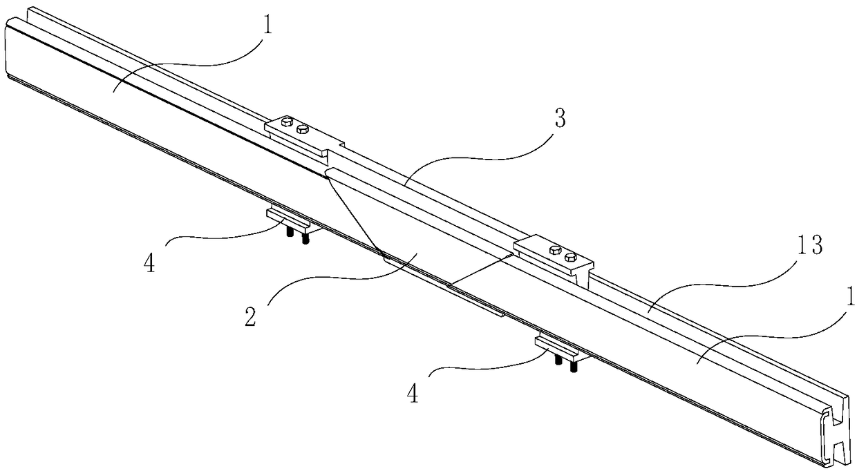
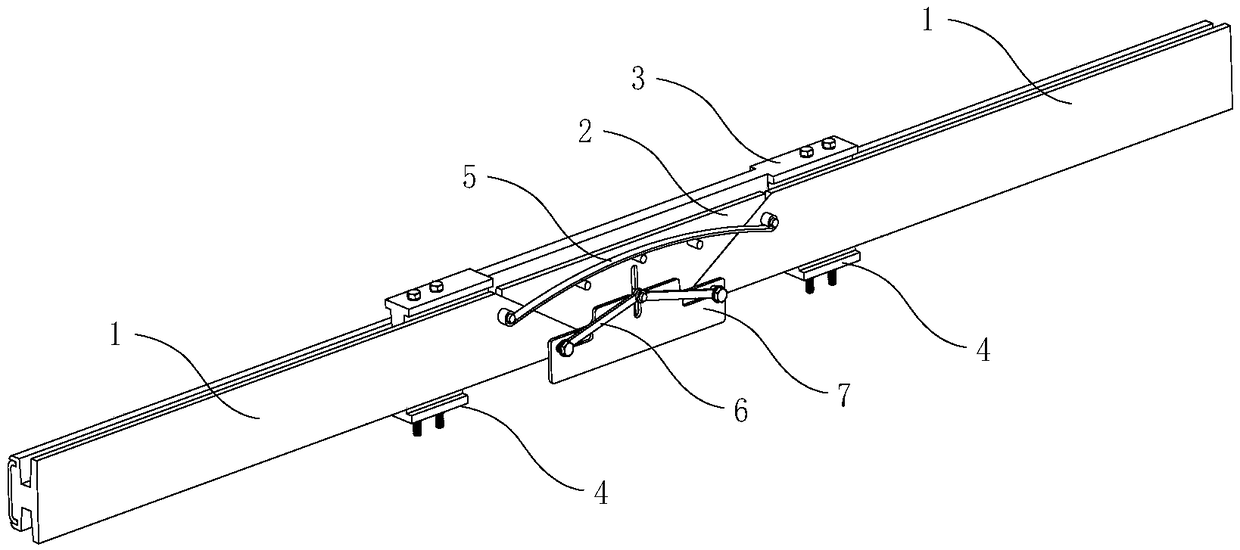
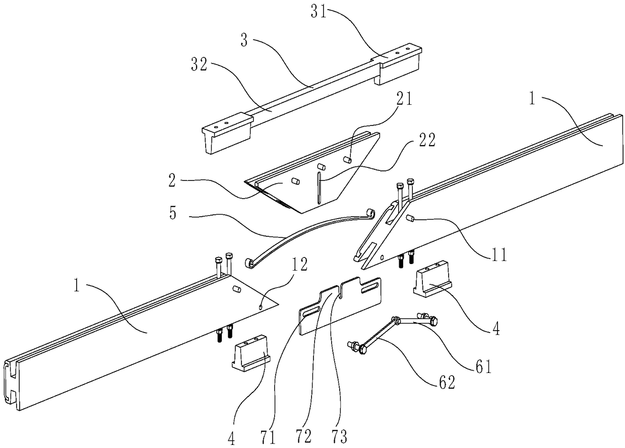
[0027] In the first specific embodiment, such as figure 1 with figure 2 As shown, the seamless contact rail expansion connection device provided by the present invention mainly includes three parts in the longitudinal direction: a trapezoidal rail 2 and two end rails 1 located at both ends of the trapezoidal rail 2, wherein the two waists of the trapezoidal rail 2 are equal.

[0028] The two cross-sections between the above three parts are completely fitted ...


PUM


Abstract

The invention discloses a seamless contact rail expansion connecting device, which comprises an isosceles trapezoidal rail and two end rails respectively located at two longitudinal ends of the trapezoidal rail. An elastic fastener is arranged between the trapezoidal rail and the two end rails so that the trapezoidal rail closely contacts the two end rails in the longitudinal direction. The end rail and the back surface of the trapezoidal rail are also provided with an automatic centering part to keep the trapezoidal rail in the longitudinal center position of the two end rails in the processof sliding relative to each other. The invention provides a seamless contact rail expansion connection device, As an automatic centering part is arranged between the end rail and the trapezoidal rail,and the end rail and the trapezoidal rail are produced by cutting the same section of the main rail, the device ensures that the trapezoidal rail is kept in the middle position of the two end rails at all times when the contact rail is thermally expanded and cold contracted, and the trapezoidal rail does not produce the transverse height difference due to the machining error when the trapezoidalrail moves relative to each other, which is favorable for the current collector to smoothly pass through the expansion joint, and ensures the continuous and stable current collection between the current collector and the contact rail.

Description

technical field [0001] The invention relates to the technical field of rail transit contact rails, in particular to a seamless contact rail expansion connection device. Background technique [0002] In the field of rail transit, especially in the field of urban rail transit, the contact rail is usually arranged on both sides of the train track along the line direction, and it is connected to a power supply network such as a substation, and is mainly used to supply power to the train. At the same time, a current receiver device for taking electricity is installed on the train. The current receiver follows the train and obtains electric energy for the train through dynamic contact with the contact rail during the running process. The dynamic contact is maintained, and the current collector slides on the current receiving surface of the contact rail during the whole process. [0003] Because the metal track is greatly affected by the external environment such as temperature, t...

Claims


Application Information

Patent Timeline
IPC IPC(8): B60M1/30
CPCB60M1/305
Inventor 梁潇李烨龙志强陈峰王武亮向婷肖溪玥文琢
Owner 湖南轨道技术应用研究中心有限公司
Learn More