
A Ship Thrust Bearing Device with Low Frequency Vibration Isolation Effect

A thrust bearing and vibration isolation technology, applied in the field of ships, can solve the problems of reducing the vibration isolation effect, shifting the shaft, inconvenient use, etc., and achieve the effects of improving the vibration isolation effect, facilitating accurate connection and simple operation.

Active Publication Date: 2019-09-27
JIMEI UNIV
View PDF8 Cites 0 Cited by
  • Summary
  • Abstract
  • Description
  • Claims
  • Application Information

AI Technical Summary

Problems solved by technology

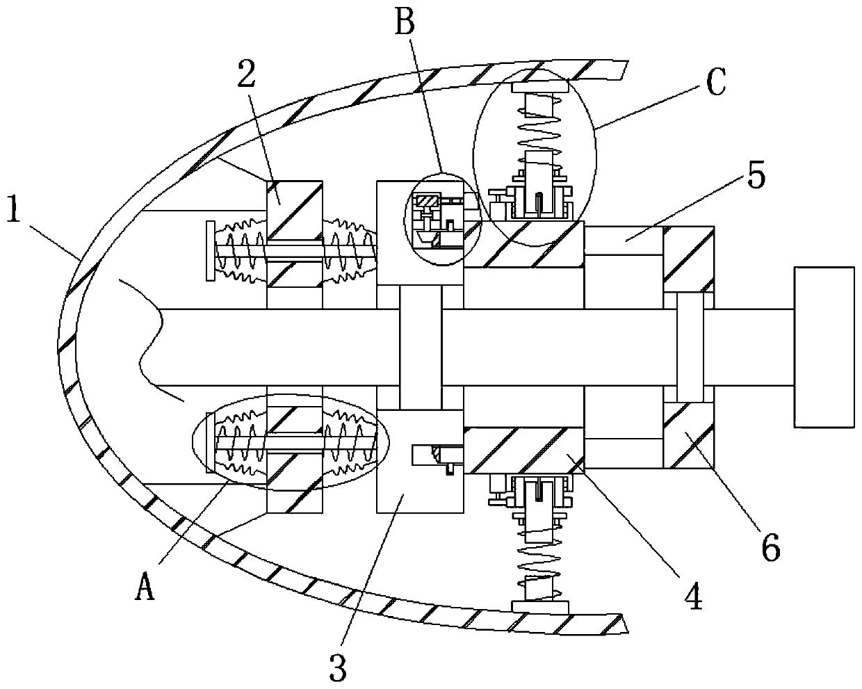
[0003] However, the above-mentioned design still has shortcomings. Since the frequency of the longitudinal excitation force of the shafting is usually low frequency or ultra-low frequency, in order to isolate the longitudinal excitation force, the natural frequency of the longitudinal vibration isolator of the thrust bearing is usually made relatively small, so that the spring It is soft, which causes the longitudinal static displacement of the thrust shaft to be too large, which is easy to cause the phenomenon of "shaft shifting"; in addition, the thrust bearing assembly cannot be rotated and fine-tuned, which is not convenient for the accurate installation of the radial vibration isolator. In addition, the thrust bearing assembly cannot It has a telescopic connection mechanism, which makes it impossible to perform telescopic adjustment, which is inconvenient to adapt to different radial vibration isolators, reduces the vibration isolation effect, and is not convenient for people to use. Therefore, a ship thrust bearing with low-frequency vibration isolation effect is proposed device

Method used


Image

  • A Ship Thrust Bearing Device with Low Frequency Vibration Isolation Effect
  • A Ship Thrust Bearing Device with Low Frequency Vibration Isolation Effect
  • A Ship Thrust Bearing Device with Low Frequency Vibration Isolation Effect

Examples


Embodiment Construction

[0023] The following will clearly and completely describe the technical solutions in the embodiments of the present invention with reference to the accompanying drawings in the embodiments of the present invention. Obviously, the described embodiments are only some, not all, embodiments of the present invention. Based on the embodiments of the present invention, all other embodiments obtained by persons of ordinary skill in the art without making creative efforts belong to the protection scope of the present invention.

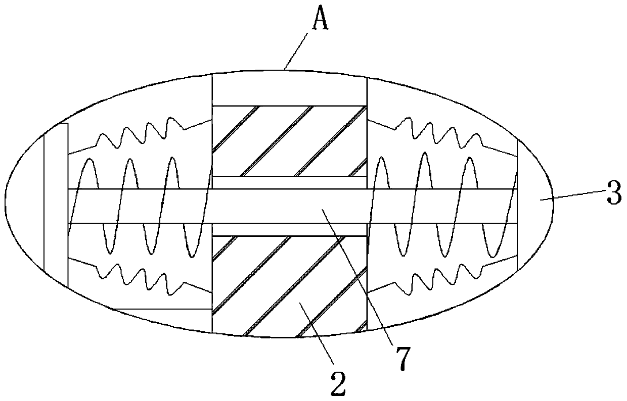
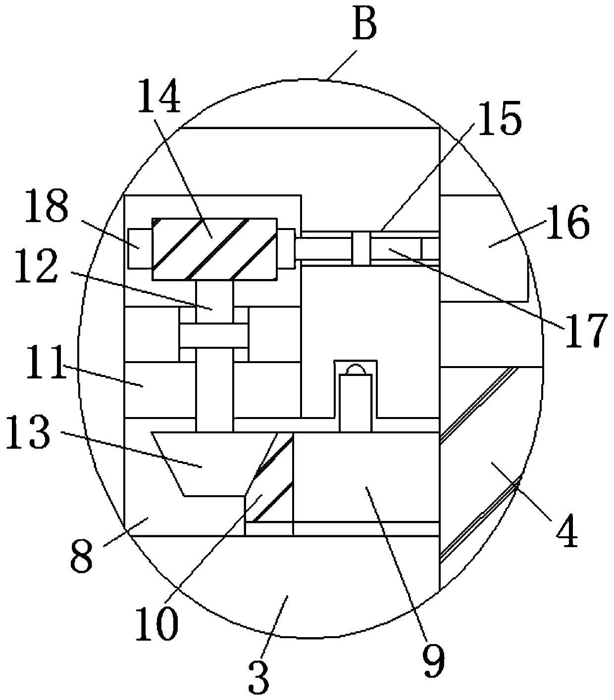
[0024] Please refer to Figure 1-5, the present invention provides a technical solution: a ship thrust bearing device with low-frequency vibration isolation effect, including an annular base 2 fixedly installed on the inner wall of the stern 1, and one side of the annular base 2 is provided with a first bushing 3. The side of the first shaft sleeve 3 away from the annular base 2 is rotatably installed with a first annular block 4, and the side of the first ann...


PUM


Abstract

The invention belongs to the technical field of ships, in particular to a marine thrust bearing device with low-frequency vibration isolation effect, comprises an annular base fixedly mounted on the stern inner wall of the ship. One side of the annular base is provided with a first shaft sleeve, a first annular clip is rotatably mounted on the side of the first shaft sleeve far away from the annular base, a plurality of support rods are welded on the side of the first annular clip far away from the first shaft sleeve, and an end of the support rods far away from the first annular clip is welded with the same second shaft sleeve. The advantage of that invention are high practicability, Simple operation, By installing a quasi-zero stiffness vibration isolator, the problem of ''shifting axis'' of the thrust shaft is avoided and the longitudinal low-frequency exciting force of the shaft system is isolated, As that power is provided by the motor, the first annular clam block can be quicklyrotated, so that the angle of the connecting mechanism of the radial vibration isolator can be adjusted to facilitate accurate connection, and the connecting mechanism can be quickly adjusted in telescopic manner to adapt to different radial vibration isolators, and the vibration isolation effect is improved.

Description

technical field [0001] The invention relates to the technical field of ships, in particular to a ship thrust bearing device with low-frequency vibration isolation effect. Background technique [0002] The quasi-zero stiffness vibration isolator is a combination of positive and negative stiffness elastic elements connected in parallel at the static equilibrium position to obtain zero stiffness. It has a large static stiffness and can bear the weight of the isolated equipment. The equipment vibrates at the static equilibrium position When the stiffness tends to zero, it is beneficial to low-frequency vibration isolation and protection equipment. With the continuous development of science and technology, quasi-zero stiffness vibration isolators are widely used, mainly in technical fields such as mining machines, generators and turbines, especially in ships. Thrust bearing equipment for turbines, after searching, the patent document with application publication number CN10789196...

Claims


Application Information

Patent Timeline
Patent Type & Authority Patents(China)
IPC IPC(8): B63H23/32
Inventor 杨志荣戴乐阳王岩柯贤勇
Owner JIMEI UNIV
Learn More