Eureka AIR delivers breakthrough ideas for toughest innovation challenges, trusted by R&D personnel around the world.

Self-propelled peeping probe adapted to different diameters of drill holes and peeping method thereof

A peeping probe that adapts to different technologies and is applied in the field of peeping probes. It can solve problems such as difficulty in pushing, difficulty in controlling the stability of the push rod, and poor imaging accuracy, so as to reduce labor intensity, speed up the efficiency of peeping operations, and avoid lengthening the push rod. Effect

Inactive Publication Date: 2019-01-08
CHINA UNIV OF MINING & TECH
View PDF8 Cites 14 Cited by
  • Summary
  • Abstract
  • Description
  • Claims
  • Application Information

AI Technical Summary

Problems solved by technology

[0004] However, under the background of the above process, there are the following problems: first, the advancing speed and range of the push rod are limited by manual operation, which may easily cause the image of key positions on the inner wall of the borehole to be unclear; second, when the drilling depth is large, the push rod The stability is difficult to control, especially during the peeking process of the roof drilling, the push rod is easily stuck by the broken rock blocks in the drilling fracture zone, which sometimes makes pushing difficult; third, it is difficult to center the peeping probe in the borehole, This leads to poor imaging accuracy, and the front edge of the peeping probe is easily scratched by the inner wall of the borehole, and debris is accumulated on the peeping probe, which deteriorates the imaging effect; fourth, the peeping process has strict requirements on the diameter of the borehole, and different diameters of boreholes need to be equipped with different diameters. Peeping probe, complex operation process, high equipment cost

Method used


Image

  • Self-propelled peeping probe adapted to different diameters of drill holes and peeping method thereof
  • Self-propelled peeping probe adapted to different diameters of drill holes and peeping method thereof
  • Self-propelled peeping probe adapted to different diameters of drill holes and peeping method thereof

Examples


Embodiment Construction

[0036] The present invention will be further described below in conjunction with the embodiment in the accompanying drawings:

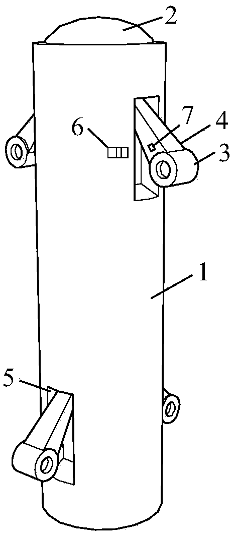
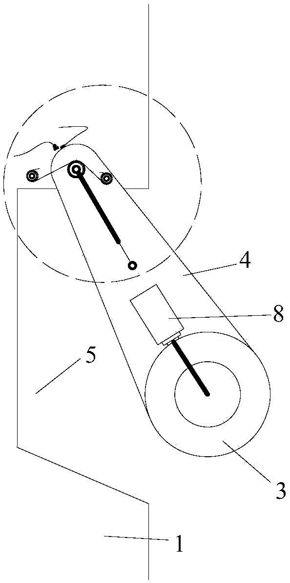
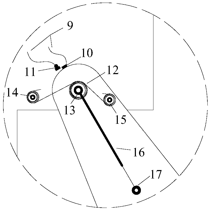
[0037] Such as figure 1 As shown, a self-propelled peeping probe adapted to different borehole diameters includes a cylindrical peeping probe body 1, a protruding camera 2 is provided on the top of the peeping probe body 1, and a connecting directional WIFI receiving line 28 is provided at the bottom The directional WIFI receiving line interface 23 and the emergency rope connection column 24 connected to the emergency rope 27, the diameter of the peeping probe main body 1 of the cylindrical shape is 35 ~ 45mm, and the height is 300-400mm; The travel control in 25 is completed by the control host 30, and the control host is connected with a directional WIFI transmitting line 29, such as Figure 6 As shown; the length of the directional WIFI receiving line 28 is 2-3m, and the length of the directional WIFI transmitting line 29 is 2-4m; the length of th...


PUM

PropertyMeasurementUnit
Diameteraaaaaaaaaa
Heightaaaaaaaaaa
Lengthaaaaaaaaaa

Abstract

The invention discloses a self-propelled peeping probe adapted to different diameters of drill holes and a peeping method thereof. The probe comprises a peeping probe body, a camera, walking wheels, rocker arms connected to the walking wheels, and an operating host. The rock arms can achieve a certain angle of damping opening and closing under the effects of internal torsion springs and gas springs and have alarm functions, and the rocker arms can be fixed in grooves of a peeping probe side through locking holes and locking blocks. The self-propelled function of the peeping probe in a drill hole can be achieved through an internal power supply, a driving motor, a video processing module, a control module, a WIFI module and the external operating host. The peeping probe has the advantages of centered drill hole, self-propelling and less workers in operation in a drilling peeping operation process, the complexity in a conventional drilling peeping operation is reduced, a push rod and a video transmission line are removed, auxiliary accessories are greatly reduced, and a new solution is provided for determining the fracture of a rock mass through drilling peeping in underground engineering.

Description

technical field [0001] The invention relates to a peeping probe and a method, in particular to a peeping probe and a peeping method which are self-propelled and adaptable to different borehole diameters, and are suitable for the fields of geotechnical engineering, mining engineering and geological exploration. Background technique [0002] In geotechnical engineering, mining engineering, and geological exploration, the internal conditions of rock formations are relatively hidden, and it is difficult to find details such as cracks, separated layers, and broken areas inside rock formations through visual observation and empirical analogy. Based on this, engineers and technicians often use borehole peepers to detect the structure of rock formations in rock formations. In addition, the borehole peeping instrument can detect the range and changes of the surrounding rock loosening circle of the roadway, test the displacement change of the surrounding rock stratum during the stress...

Claims


Application Information

Patent Timeline
IPC IPC(8): E21B47/002E21B47/13
CPCE21B47/002E21B47/13
Inventor 冯晓巍张农谢正正刘洋
Owner CHINA UNIV OF MINING & TECH
Why Eureka
Eureka Blog
Learn More