Oil spray nozzle

A technology of fuel injectors and fuel injection holes, which is applied in the field of anti-carbon deposition nozzles, which can solve problems such as carbon deposits in fuel injectors, coking of fuel injection holes, and affecting spray effects, so as to reduce residues and reduce carbon deposits. Effect

Pending Publication Date: 2019-01-08
ZHEJIANG BATON DYNAMICS SYST CO LTD
View PDF0 Cites 2 Cited by
  • Summary
  • Abstract
  • Description
  • Claims
  • Application Information

AI Technical Summary

Problems solved by technology

However, after fuel injection, there will be some oil remaining in the valve body, which will easily form a large amount of insoluble and interconnected polymeric network viscous substances, which will gradually accumulate and eventually form coking in the fuel injection hole, resulting in carbon deposits inside the fuel injector. If it is serious, it will eventually block the oil injection hole and affect the spray effect

Method used


Image

  • Oil spray nozzle
  • Oil spray nozzle
  • Oil spray nozzle

Examples


Embodiment 1

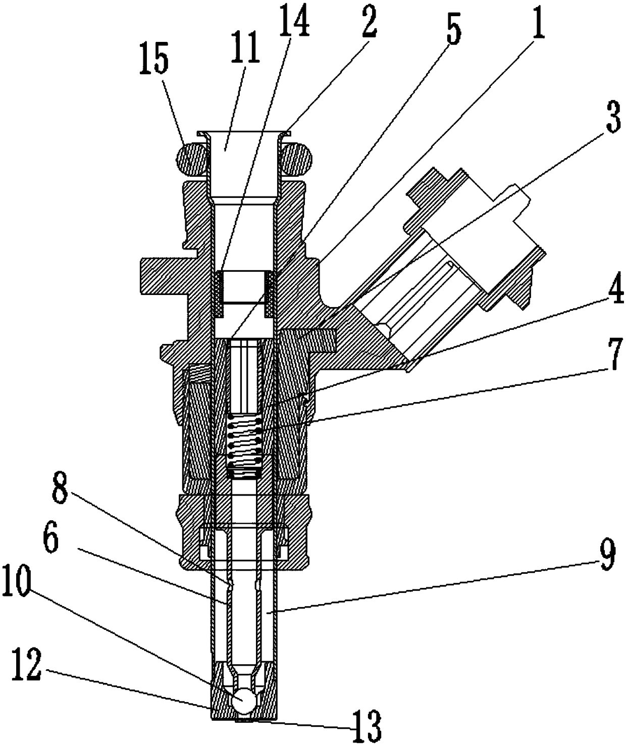
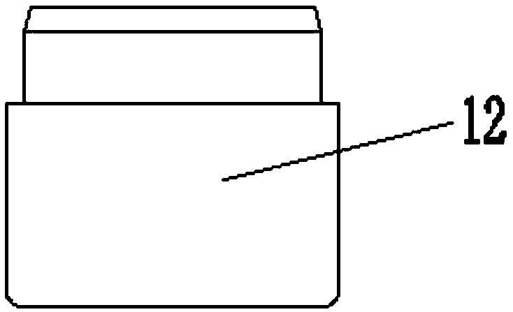
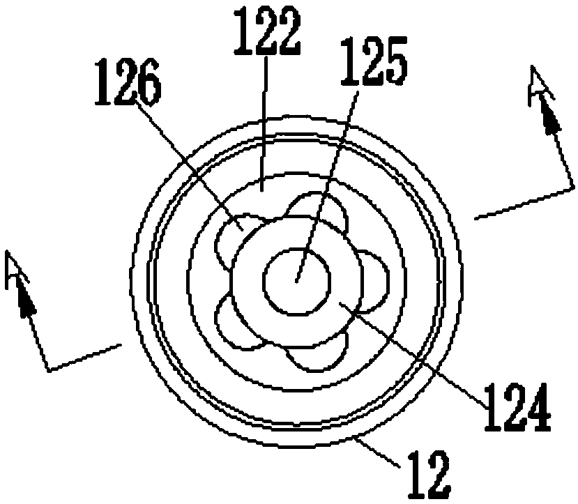
[0041] Such as Figure 1-12 As shown, this embodiment discloses a fuel injector, which can be a fuel injector, a gas injector or a urea injector. The fuel injection nozzle includes a housing 1. The housing 1 may be the housing of the fuel injection nozzle mentioned above in the prior art, and is usually composed of several matching structures; the housing 1 is provided with The valve body 2 can be the valve body structure of the above-mentioned fuel injection nozzle in the prior art; a coil assembly 3 is arranged between the housing 1 and the valve body 2, the coil assembly 3 It can be a combination of existing structures, such as a coil former arranged between the housing 1 and the valve body 2, a coil surrounding the coil former, a positive and negative electrode structure connecting the two poles of the coil, etc.; In order to set the structure for controlling the movement of the valve core 6 in the valve body 2 in a position that matches the coil assembly 3, an adjusting s...


PUM


Abstract

The invention discloses an oil spray nozzle. A first frustum cavity with a broad upper part and a narrow lower part is formed in a valve seat, so that pressure when a medium such as an oil liquid passes through becomes large, at the same time, a converging flow groove is also formed, so that the medium such as the oil liquid can quickly reach an oil outlet hole and be discharged while the pressurebecomes large, and carbon deposit caused by the fact that the medium such as the oil liquid is retained in a valve body is avoided; and furthermore, a first cylindrical cavity, a first frustum cavity, a second cylindrical cavity, a second frustum cavity and the oil outlet hole are arranged on the valve seat, wherein the first cylindrical cavity, the first frustum cavity, the second cylindrical cavity, the second frustum cavity and the oil outlet hole communicate with each other. According to the oil spray nozzle, a channel through which the medium such as the oil liquid passes through the valve seat (or a partition plate) is simplified, the medium such as the oil liquid retaining in the valve body and/or the valve seat is reduced, so that the carbon deposit is reduced.

Description

Technical field [0001] The invention relates to the technical field of fuel injection nozzles, in particular to an anti-carbon deposition fuel injection nozzle. Background technique [0002] The fuel injector is one of the key components of the EFI engine, and its performance will seriously affect the performance of the engine. Existing fuel injection nozzles generally have a simple solenoid valve structure. For example, CN2016209634863 discloses a nozzle that includes a housing, a valve body is arranged in the housing, and a coil assembly is arranged between the valve body and the housing. The valve body is provided with an adjusting sleeve and a valve core, the valve core can slide in the valve body, a spring fixing seat is arranged in the adjusting sleeve, and an elastic member is arranged between the spring fixing seat and the valve core, so The front end of the valve core passes through the partition plate and the nozzle is provided with a ball, the valve core is provided w...

Claims


Application Information

Patent Timeline
Patent Type & Authority Applications(China)
IPC IPC(8): F02M61/04F02M61/16F02M61/18
CPCF02M61/188F02M61/04F02M61/165
Inventor 林友贵陈文辉蔡洪林海
Owner ZHEJIANG BATON DYNAMICS SYST CO LTD
Why Eureka
Try Eureka