Condensation dehumidifying device based on semiconductor chilling plate
What is Al technical title?
Al technical title is built by PatSnap Al team. It summarizes the technical point description of the patent document.
A refrigeration chip and semiconductor technology, applied in the direction of preventing condensed water, heating and ventilation control systems, and control input involving air characteristics, etc., can solve the problems of accelerating the aging of surrounding cables and equipment, affecting the normal operation of equipment, and existing safety hazards. Achieve the effect of increasing rapid condensation and drainage settings, solving humidity problems, and lasting in dry environments
Pending Publication Date: 2019-01-08
广西鑫百纳电气有限公司
View PDF7 Cites 7 Cited by
Summary
Abstract
Description
Claims
Application Information
AI Technical Summary
This helps you quickly interpret patents by identifying the three key elements:
Problems solved by technology
Method used
Benefits of technology
Problems solved by technology
However, the moisture is still in the electric cabinet. When the temperature difference is large, the moisture in the air will condense on the surface of the equipment, which will still affect the normal operation of the equipment.
Moreover, the product itself generates heat during operation, which will accelerate the aging of surrounding cables and equipment, and even damage the cable insulation, posing a safety hazard.
Method used
Image
Click on the blue label to locate the original text in one second.
Reading with bidirectional positioning of images and text.
Examples
Embodiment Construction
[0024] The specific embodiments of the present invention will be described in detail below in conjunction with the accompanying drawings, but it should be understood that the protection scope of the present invention is not limited by the specific embodiments.
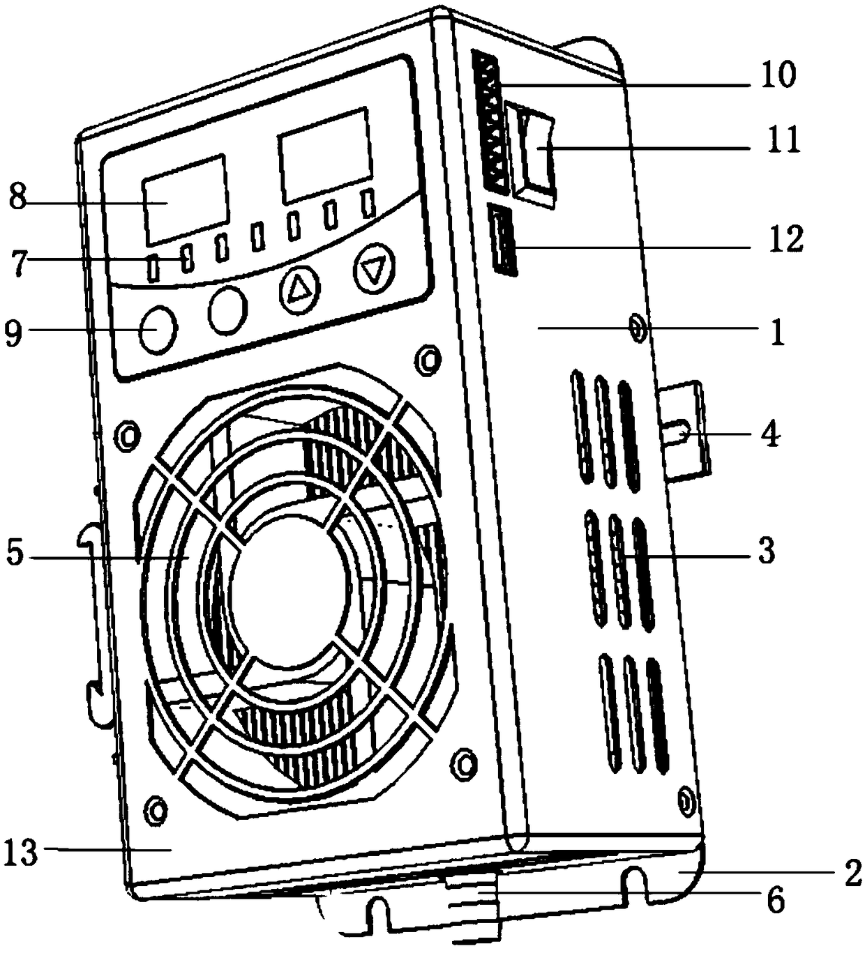
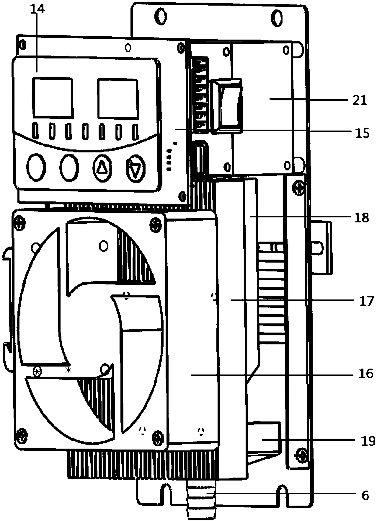
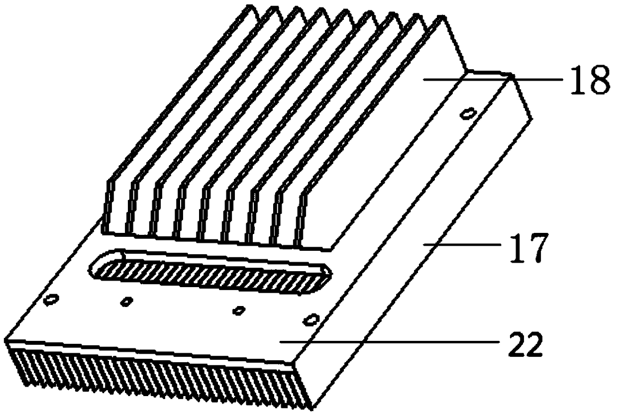
[0025] Figure 1-Figure 4 It shows the structural diagram of the condensing and dehumidifying device based on the peltier cooler according to the preferred embodiment of the present invention.
[0026] Such as Figure 1-Figure 4 As shown, in this embodiment, the condensation dehumidification device based on semiconductor cooling chips includes: housing 1, control panel 14, main board 15, fan 16, heat sink 17, semiconductor cooling chips 20, cooling fins 18, water receiving tank 19, sponge Pad 22, hydrophilic material coating and temperature and humidity sensor. The housing 1 preferably adopts a detachable structural design, such as including a bottom plate 2 and a top cover 13, the bottom plate 2 and the top cover 13...
PUM
Abstract
The invention relates to the field of dehumidifying equipment, in particular to a condensation dehumidifying device based on a semiconductor chilling plate. The condensation dehumidifying device basedon the semiconductor chilling plate comprises a shell, a main board control circuit arranged in the shell, a fan, heat dissipation fins, the semiconductor chilling plate, cooling fins, a water receiving groove, a sponge mat and hydrophilic material coatings, wherein an air suction opening of the fan, the heat dissipation fins, the semiconductor chilling plate and the cooling fins are arranged inthe shell in a sequential attaching manner, the fan and the semiconductor chilling plate are connected with the main board control circuit, an air inlet is formed in the position, corresponding to theair suction opening of the fan, of the shell, and an air outlet is formed in the position, corresponding to the air blowing direction of the fan, of the shell; the water receiving groove is arrangedin the position to which water drops coagulated on the cooling fins drop, and a water outlet of the water receiving groove extends to the exterior of the shell; the sponge mat is arranged between theheat dissipation fins and the cooling fins; and the hydrophilic material coatings are arranged on the surfaces of the cooling fins. According to the condensation dehumidifying device, condensation dehumidifying is achieved through the temperature difference generated by the semiconductor chilling plate, meanwhile, by additionally arranging rapid water condensation and water discharging, the dehumidifying speed is higher, and the dry environment can be kept longer.
Description
technical field [0001] The invention belongs to the field of dehumidification equipment, and in particular relates to a condensation dehumidification device based on semiconductor refrigeration chips. Background technique [0002] Power production equipment is the vitality of every enterprise and the core of life. It is also the main tool for enterprises to create profits. Today's industrial production processes are increasingly automated. Ambient temperature and humidity are an important factor affecting whether electrical equipment can work normally. If the ambient temperature and humidity are too high, the temperature rise of electrical equipment will also increase, causing the aging of the insulation device to accelerate, and even burning the insulation device in severe cases. Excessive air humidity will cause moisture to condense on the surface of the equipment, which will accelerate the growth of mold, which will lead to a decrease in the electrical insulation streng...
Claims
Application Information
Patent Timeline
Application Date:The date an application was filed.
Publication Date:The date a patent or application was officially published.
First Publication Date:The earliest publication date of a patent with the same application number.
Issue Date:Publication date of the patent grant document.
PCT Entry Date:The Entry date of PCT National Phase.
Estimated Expiry Date:The statutory expiry date of a patent right according to the Patent Law, and it is the longest term of protection that the patent right can achieve without the termination of the patent right due to other reasons(Term extension factor has been taken into account ).
Invalid Date:Actual expiry date is based on effective date or publication date of legal transaction data of invalid patent.