Chemical production equipment and working method thereof

A technology for chemical production and working methods, applied in the chemical industry, which can solve the problems of occupation, time difference, low work efficiency, etc.

Inactive Publication Date: 2019-01-08
东阳市新意工业产品设计有限公司
View PDF9 Cites 1 Cited by
  • Summary
  • Abstract
  • Description
  • Claims
  • Application Information

AI Technical Summary

Problems solved by technology

[0006] However, this will cause a problem, that is, the time required for each chemical material to dry is different, and if the time is monitored manually and the material is taken out, it will inevitably cause low work efficiency and occupy more staff of

Method used


Image

  • Chemical production equipment and working method thereof
  • Chemical production equipment and working method thereof
  • Chemical production equipment and working method thereof

Examples


no. 1 example

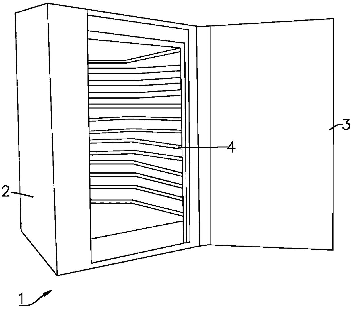
[0042] The chemical production equipment in this embodiment includes a transport assembly 10 and an oven 20 .

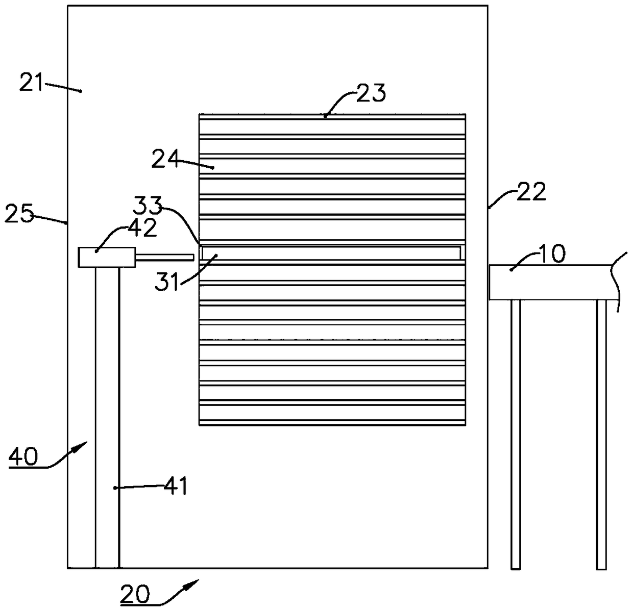
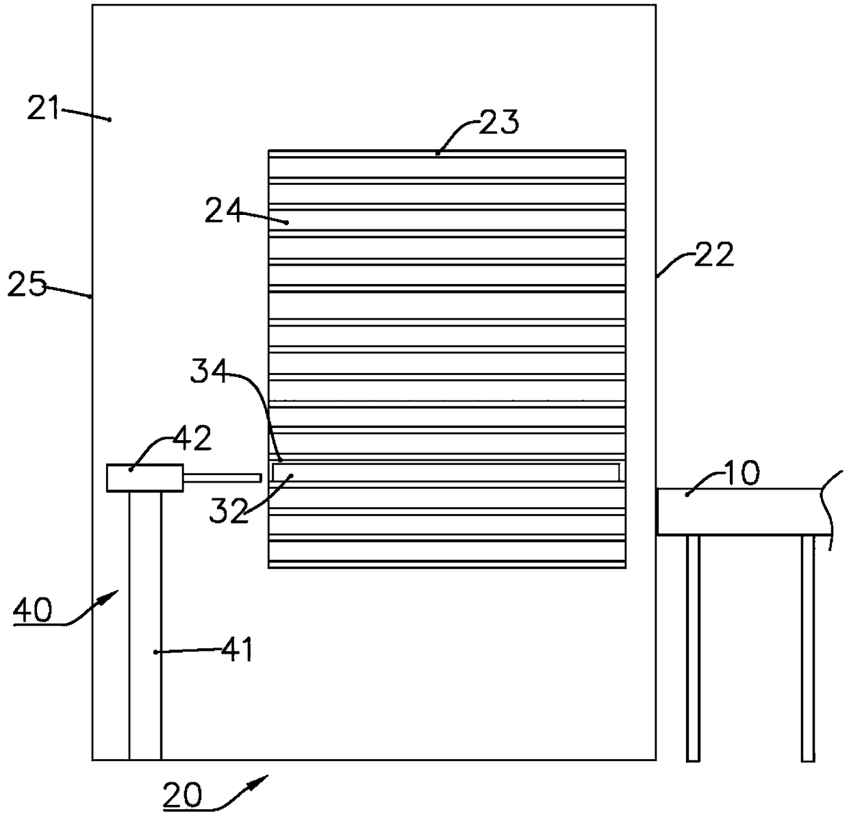
[0043] Such as Figure 2 to Figure 5 As shown, the oven 20 is connected to the transfer assembly 10 . Wherein, the oven 20 includes a box body 21 , the box body 21 includes a door body 22 , and a frame body 23 is arranged inside the box body 21 , and the frame body 23 has a multi-layer compartment 24 for placing the tray body 30 . The tray body 30 is used for loading materials to be dried.

[0044] The box body 21 has a rear wall 25, and the position between the rear wall 25 and the frame body 23 is provided with a removal assembly 40. The removal assembly 40 includes a lift unit 41, and the lift unit 41 is provided with a lateral push unit 42. The lateral push unit 42 Used to push the tray 30 placed on the compartment 24 onto the transfer assembly 10 . The lifting unit 41 may specifically be a screw, which is driven by a motor, thereby driving the horizontal push...

no. 2 example

[0052] The chemical production equipment of this embodiment is basically the same as that of the above-mentioned first embodiment, and only the differences will be described in detail below.

[0053] Such as Figure 6 and Figure 7 As shown, the door body 22 of this embodiment has an opening 26 , and a push-pull assembly 50 is disposed on the top of the opening 26 , and the push-pull assembly 50 includes a push-pull unit 51 and a shielding board 52 . The push-pull unit 51 is, for example, an air cylinder or a hydraulic cylinder to push the telescopic rod to move, thereby driving the shielding plate 52 to shield or open the opening 26 . In the open state, the tray body 30 can enter or leave the box body 21 driven by other components, and in the closed state, the drying operation can be performed in the box body 21 .

[0054] The working method includes the following steps: the push-pull unit 51 drives the shielding plate 52 to move in the vertical direction, and the shielding...

no. 3 example

[0056] The chemical production equipment of this embodiment is basically the same as that of the above-mentioned first embodiment, and only the differences will be described in detail below.

[0057] Such as Figure 8 As shown, the transmission assembly 10 of this embodiment includes a support unit 11, a lifting mechanism 12 is provided at the lower part of the support unit 11, and the support unit 11 includes a plurality of rotating rollers 13 arranged in sequence, and the rollers 13 are used to transport the disk 30 . The lifting mechanism 12 is preferably a motor-driven screw structure, and the screw drives the support unit 11 to move in the vertical direction, so that the upper surface of the support unit 11 corresponds to the disc body 30 that is pushed out of the box body 21, so that it is pushed out The disc body 30 moves onto the support unit 11 . In addition, the height of the support unit 11 can also be manually adjusted, so that the height of the pushed out tray b...


PUM


Abstract

The invention discloses chemical production equipment, comprising a transmission assembly and an oven; the oven is connected with the transmission assembly, wherein the oven comprises a box body whichcomprises a door body; the box body is internally provided with a frame body; the frame body is provided with a multi-layer compartment which is used for placing disk bodies; materials to be dried are loaded in each disk body; the box body is provided with a rear wall; a removing assembly is arranged at the position between the rear wall and the frame body; the removing assembly comprises a lifting unit; a horizontal pushing unit is arranged on the lifting unit; the horizontal pushing unit is used for pushing each disk body placed on the compartment to the transmission assembly. The unattended drying process is realized; when some disk body is dried, the lifting unit moves to a certain height and pushes the disk body out of the box body by the horizontal pushing unit; thus different kindsof materials can be dried in the same box body; and after the time reaches a certain stage, the dried disk body can be removed out automatically.

Description

technical field [0001] The technical field related to the present invention belongs to the field of chemical industry, in particular to an oven for chemical production equipment and its working method. Background technique [0002] my country is a big country in the chemical industry, which has a profound impact on all fields of the national economy. Commodities formed by the chemical industry have penetrated into every aspect of people's daily life. [0003] There are many types of chemical equipment, and each chemical equipment has its fixed function. Only when multiple equipment cooperates can products that meet the requirements be produced. [0004] Oven is a very important chemical equipment, its main function is to remove solvent from chemical materials to achieve the purpose of drying. In particular, larger ovens are frequently used in daily chemical production and are often in a continuous working state. [0005] Such as figure 1 Shown is an existing oven 1, whic...

Claims


Application Information

Patent Timeline
IPC IPC(8): F26B9/06F26B25/00
CPCF26B9/066F26B25/003
Inventor 俞俊越
Owner 东阳市新意工业产品设计有限公司
Why Eureka
Try Eureka