Method for amplifying beam structure and improving amplitude ratio in blade vibration fatigue test

A vibration fatigue and beam structure technology is applied in the field of amplifying the beam structure and improving the amplitude ratio in the blade vibration fatigue test. Achieve the effect of increasing the power amplification factor, increasing the amplitude ratio, and increasing the first-order resonance frequency

Pending Publication Date: 2019-01-08
苏州长菱测试技术有限公司
View PDF0 Cites 6 Cited by
  • Summary
  • Abstract
  • Description
  • Claims
  • Application Information

AI Technical Summary

Problems solved by technology

[0004] However, the first-order resonance frequency of the beam structure fixture is difficult to design above 3000 Hz, so the magnification of the beam structure fixture with a frequency above 3000 Hz will not be very high, that is, the magnification factor of the magnifying fixture to the thrust of the shaking table is not high, so that the transmission to The excitation force on the blade is not enough

Method used


Image

  • Method for amplifying beam structure and improving amplitude ratio in blade vibration fatigue test
  • Method for amplifying beam structure and improving amplitude ratio in blade vibration fatigue test
  • Method for amplifying beam structure and improving amplitude ratio in blade vibration fatigue test

Examples


Embodiment 1

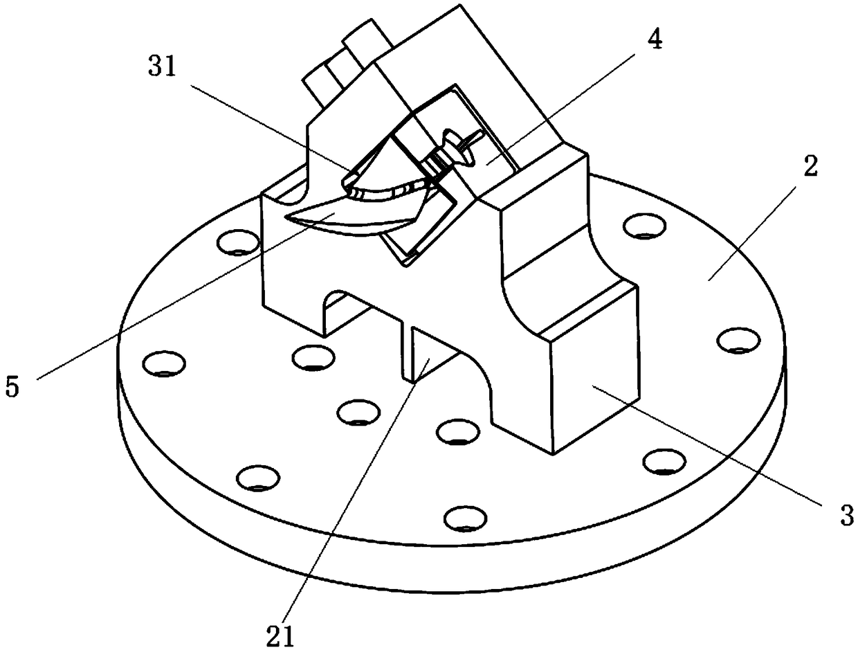
[0040] An enlarged beam structure, refer to figure 1 with figure 2 , including a base 2, the base 2 is provided with a clip body 3 for fixing the blade 5, and the clip body 3 and the base 2 are fixedly connected. When the vibration fatigue test is carried out on the blade 5, the base 2 is fixed above the vibrating table for providing thrust, and the clamp body 3 can amplify the thrust transmitted from the vibrating table to the base 2 by a certain multiple; The upper blade 5 is subjected to vibration fatigue test. At present, the maximum thrust of the vibrating table used in the market is about 500kN, but due to the large structure and mass of the moving coil, the resonance frequency of the moving coil is relatively low, so its working frequency is generally within 1500Hz, which is far from meeting the test requirements; If you choose a vibrating table with a moving coil structure and a small mass, although its operating frequency is high, its maximum thrust cannot meet the...

Embodiment 2

[0085] A method for improving the amplitude ratio in the blade vibration fatigue test, referring to Figure 7 , the excitation coil 15 of the entire vibration test system is connected to a DC power supply, and a magnetic field is established in the vibrating table body 11 to generate a high magnetic flux. Connect the driving coil 14 with alternating current, and electromagnetic force will be generated on the winding of the driving coil 14, so that the moving coil 12 can move up and down.

[0086] The load and the moving coil 12 are rigidly connected by 14 M12 screws. Since the electric vibrating table is designed based on Ampere's law, its thrust is the electromagnetic force. The formula of the electromagnetic force is:

[0087] F=BLi=BLIsinωt Formula 8

[0088] In the formula:

[0089] B—magnetic induction

[0090] L—the effective length of the moving coil winding

[0091] i—i=Isinωt, alternating current in the moving coil

[0092] ω—the frequency of the signal generat...


PUM


Abstract

The invention discloses a method for amplifying a beam structure and improving an amplitude ratio in a blade vibration fatigue test. The method is applied to the blade vibration fatigue test, and comprises a base, an amplifying body and a fixture body are arranged on the base, the fixture body is fixed above the magnifying body, and the fixture body and the magnifying body are integrally arranged;and a pressing block is arranged on the fixture body, the pressing block can be fixed with a blade through a connecting component, the connecting component comprises a tenon and a mortise, the mortise is formed in the pressing block, and the blade comprises the tenon that can be embedded in the mortise. The amplitude ratio in the vibration fatigue test can be improved, so that the blade vibrationfatigue test with relatively large exciting force and relatively high frequency can be implemented.

Description

technical field [0001] The invention relates to the field of vibration testing, in particular to a method for enlarging a beam structure and improving the amplitude ratio in a blade vibration fatigue test. Background technique [0002] Periodic airflow excitation force can cause compressor blades (hereinafter referred to as blades) to resonate, resulting in their vibration fatigue failure. Through the blade vibration fatigue test, the fatigue strength can be measured. Use an electric vibration table (hereinafter referred to as the vibration table) to excite the blade to make the blade resonate. Through the calibration relationship between the displacement of the control point on the blade and the stress, the displacement of the blade when it reaches the specified stress can be obtained. For the frequency within the working frequency range of the vibration table In the blade mode, the control system can provide enough drive to make the vibrating table reach the corresponding ...

Claims


Application Information

Patent Timeline
Patent Type & Authority Applications(China)
IPC IPC(8): G01M7/02
CPCG01M7/022
Inventor 杨友钢陈婷
Owner 苏州长菱测试技术有限公司
Why Eureka
Try Eureka