Multi-layer column leaching device for soil pollutant leaching
A pollutant, multi-layer column technology, applied in the field of soil remediation, can solve the problem of easy stasis of the extract, and achieve the effects of improving the extraction efficiency, improving the utilization rate, and reducing the difference of extraction.
- Summary
- Abstract
- Description
- Claims
- Application Information
AI Technical Summary
Problems solved by technology
Method used
Image
Examples
Embodiment 1
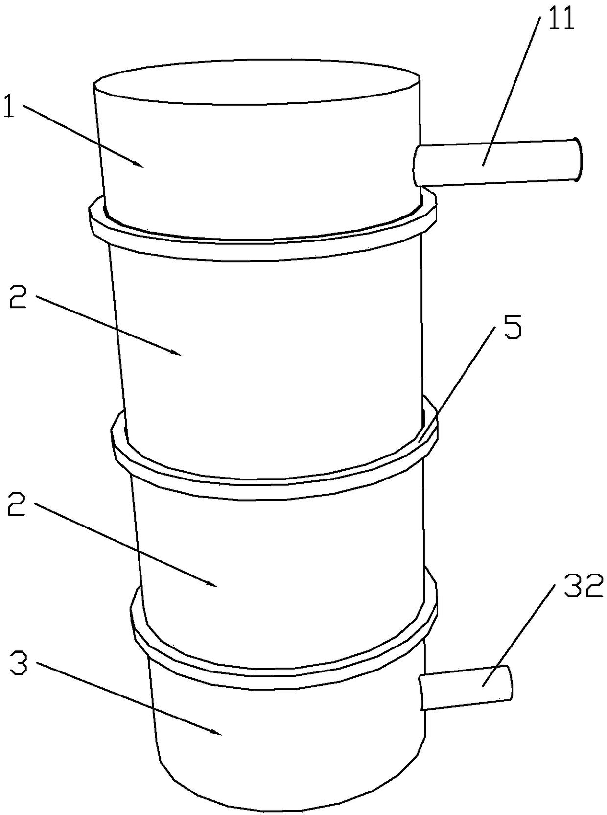
[0035] A multi-layer column leaching device for leaching of soil pollutants, comprising a liquid distribution unit 1 for distributing the leaching solution, a leaching unit 2 for extracting pollutants, and a collection unit 3 for collecting the leaching solution , the liquid distribution unit 1, the extraction unit 2 and the collection unit 3 are sequentially detachably connected, and the extraction liquid flows through the liquid distribution unit 1, the extraction unit 2 and the collection unit in sequence 3. When in use, the column leaching device is placed horizontally, the collection unit 3 is located at the bottom, the extraction unit 2 is located at the top of the collection unit 3, the liquid distribution unit 1 is located at the top of the extraction unit 2, and the extraction liquid flows into the liquid distribution unit through the tube peristaltic pump In 1, it flows through the leaching unit 2 in sequence, and is finally enriched in the collecting unit.
[0036]...
Embodiment 2
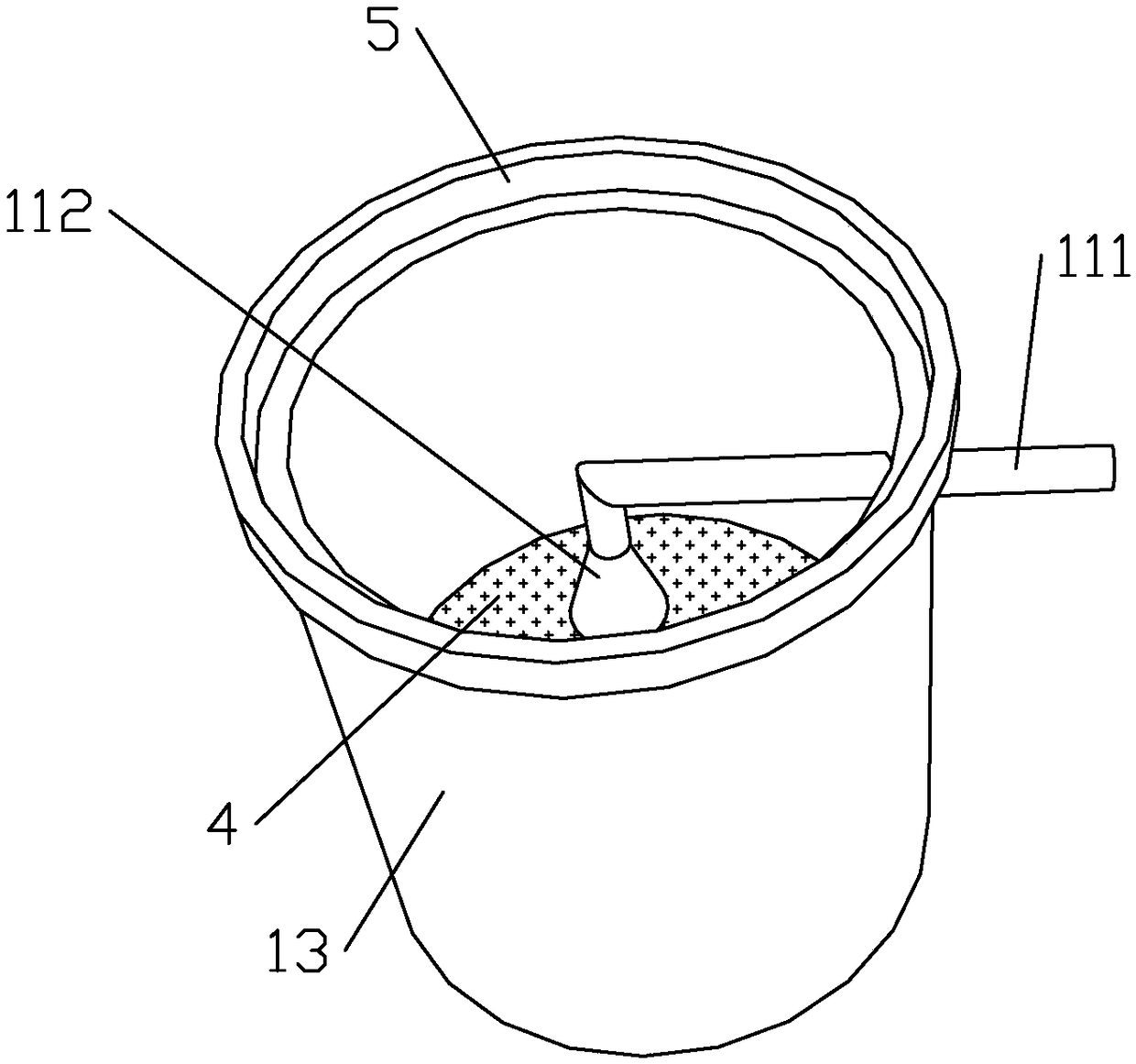
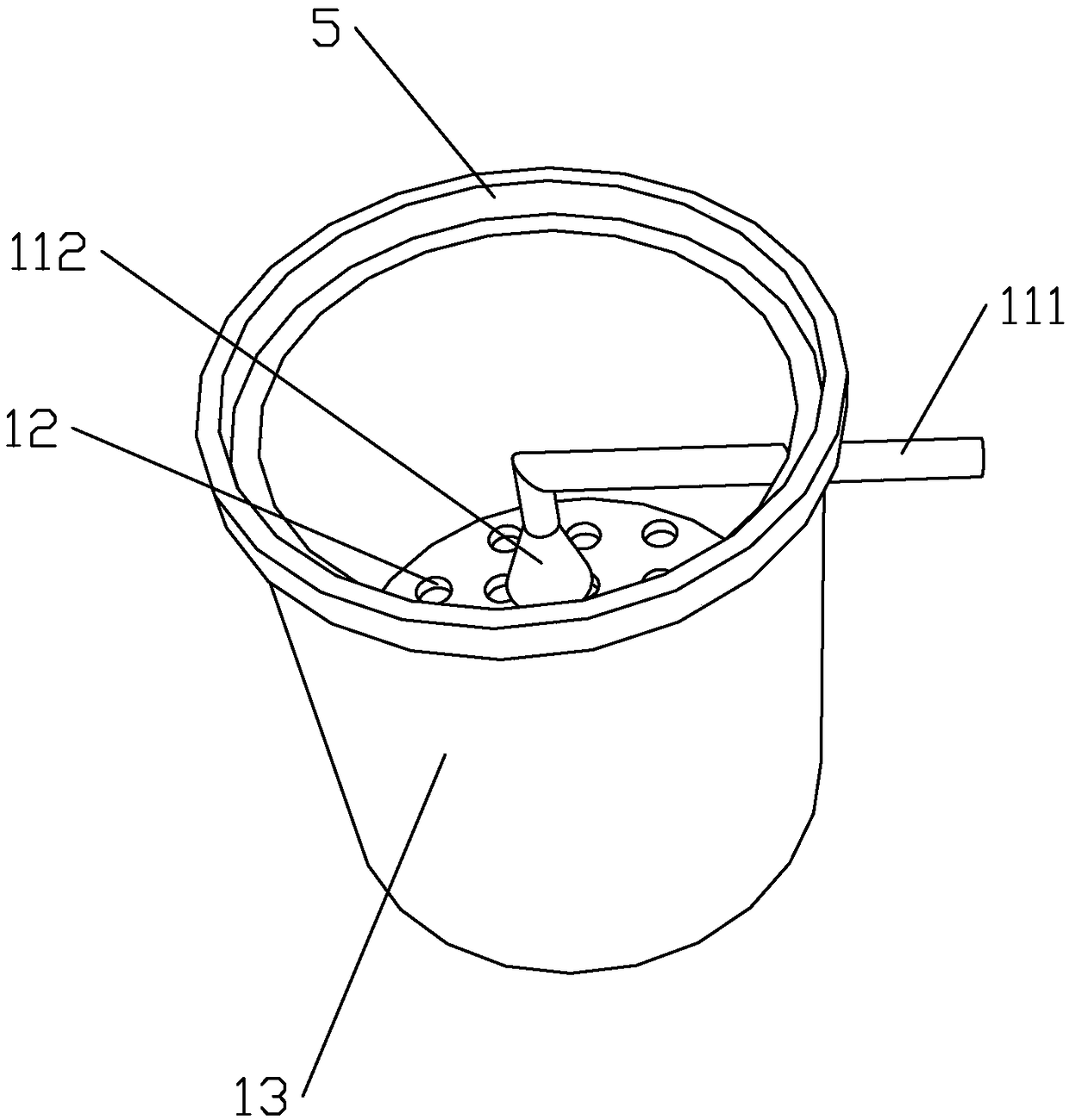
[0045] On the basis of Embodiment 1, in this embodiment, a card slot 5 is provided on the top of the collection tube 31, as shown in the attached Figure 2-5 As shown, correspondingly, a slot 5 is also provided on the top of the extraction tube 22. When assembling, the collection tube 31 is placed on a horizontal plane, and the bottom of the extraction tube 22 is placed in the slot 5 on the top of the collection tube 31. Inside, the clamping groove 5 limits the position of the extraction cylinder 22 in the horizontal direction, and supports the extraction cylinder 22 at the same time, so that the extraction cylinder 22 is stuck in the clamping groove, but the extraction cylinder 22 can be lifted upwards under the action of external force. ; Similarly, place the bottom of the liquid distribution cylinder 13 in the slot 5 on the top of the extraction cylinder 22 . Through the way of the card slot 5, each unit can be detachably connected, which is convenient for assembly, simple ...
Embodiment 3
[0047] On the basis of Embodiment 1, a cover body 6 is provided on the top of the liquid distribution cylinder 13, and the cover body 6 is threadedly connected with the liquid distribution cylinder 13, and the cover body can seal the liquid distribution cylinder 13 to prevent volatile extracts from To pollute the air, impurities can also be prevented from entering the liquid distribution cylinder 13 .
[0048] In other embodiments of the present invention, a card slot 5 may also be provided on the top of the liquid distribution cylinder, and the bottom plate of the cover 6 is placed in the card slot 5, and the cover 6 and the card slot 5 are detachably connected.
PUM
| Property | Measurement | Unit |
|---|---|---|
| thickness | aaaaa | aaaaa |
Abstract
Description
Claims
Application Information
 - R&D
- Intellectual Property
- Life Sciences
- Materials
- Tech Scout
- Unparalleled Data Quality
- Higher Quality Content
- 60% Fewer Hallucinations
Browse by: Latest US Patents, China's latest patents, Technical Efficacy Thesaurus, Application Domain, Technology Topic, Popular Technical Reports.
© 2025 PatSnap. All rights reserved.Legal|Privacy policy|Modern Slavery Act Transparency Statement|Sitemap|About US| Contact US: help@patsnap.com


