
Protective circuit and display drive device

A protection circuit, voltage threshold technology, applied in circuit devices, emergency protection circuit devices, emergency protection circuit devices for limiting overcurrent/overvoltage, etc., can solve problems such as driver chip damage, and achieve the effect of stable working characteristics

Active Publication Date: 2019-01-08
HKC CORP LTD
View PDF4 Cites 4 Cited by
  • Summary
  • Abstract
  • Description
  • Claims
  • Application Information

AI Technical Summary

Problems solved by technology

[0004] Based on this, it is necessary to provide a protection circuit and a display drive device for the problem of damage to the drive chip caused by electrical overstress

Method used


Image

  • Protective circuit and display drive device
  • Protective circuit and display drive device
  • Protective circuit and display drive device

Examples


Embodiment Construction

[0037] In order to better understand the purpose, technical solution and technical effect of the present invention, the present invention will be further explained below in conjunction with the accompanying drawings and embodiments. At the same time, it is stated that the embodiments described below are only used to explain the present invention, and are not intended to limit the present invention

[0038] An embodiment of the present invention provides a protection circuit.

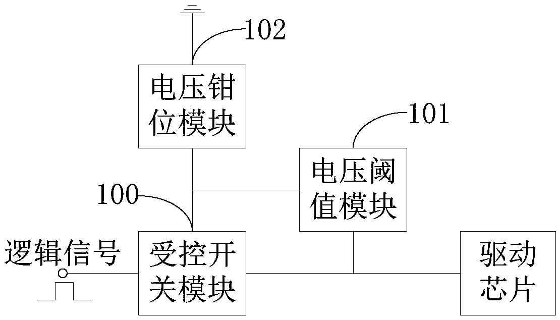
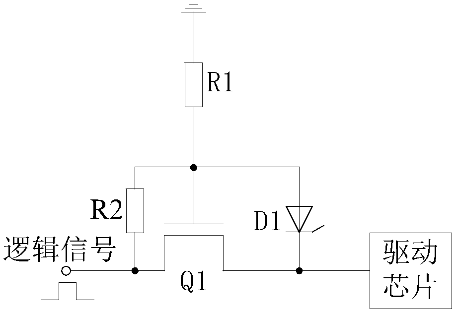
[0039] figure 1 It is a structural diagram of a protective circuit module in an embodiment, such as figure 1 As shown, the protection circuit in one embodiment includes a controlled switch module 100, a voltage threshold module 101 and a voltage clamp module 102;

[0040] The input terminal of the controlled switch module 100 is used to access the logic signal, the output terminal of the controlled switch module 100 is used to connect the input terminal of the driver chip, and the controlled terminal o...


PUM


Abstract

The invention relates to a protective circuit and a display driving device, The voltage at the output end of the controlled switch module is larger than the first preset voltage, so that the voltage threshold module is turned on, so that the input end and the output end of the controlled switch module are turned off, and the driving chip is prevented from being damaged due to the influence of theelectric overstress. At the same time, the voltage clamping module clamps the voltage potential of the controlled switch module to stabilize the operating characteristics of the controlled switch module.

Description

technical field [0001] The invention relates to the technical field of liquid crystal display equipment, in particular to a protection circuit and a display driving device. Background technique [0002] A liquid crystal display panel is a display device composed of a certain number of color or black and white pixels placed in front of a light source or reflective surface. Among them, TFT-LCD (Thin Film Transistor Liquid Crystal Display, thin film transistor liquid crystal display panel) is one of the main varieties of current liquid crystal display panels, and has become an important display platform in modern IT and video products. Taking the display driver of TFT-LCD as an example, the system motherboard connects the R / G / B compressed signal, control signal and power supply to the connector on the PCB board through wires, and the data passes through the TCON (Timing Controller, timing controller) on the PCB board. ) After the IC is processed, it is connected to the display...

Claims


Application Information

Patent Timeline
Patent Type & Authority Applications(China)
IPC IPC(8): G09G3/36
CPCG09G3/3696G09G3/36G09G2330/04H02H3/202H02H3/20H02H9/025H01L27/02
Inventor 黄笑宇
Owner HKC CORP LTD
Learn More