A variable turn pitch planar helical coil

A technology of planar spiral coil and turn spacing, applied in the direction of transformer/inductor coil/winding/connection, transformer, transformer/inductor parts, etc., can solve the problem of poor practicability and achieve the effect of slowing down the problem of copper loss

Active Publication Date: 2019-01-08
WUHAN UNIV OF TECH
View PDF5 Cites 9 Cited by
  • Summary
  • Abstract
  • Description
  • Claims
  • Application Information

AI Technical Summary

Problems solved by technology

However, this solution needs to change the wire gauge to meet the different requirements of the w...

Method used


Image

  • A variable turn pitch planar helical coil
  • A variable turn pitch planar helical coil
  • A variable turn pitch planar helical coil

Examples


Embodiment Construction

[0022] The present invention will be further described in detail below in conjunction with the accompanying drawings and specific embodiments.

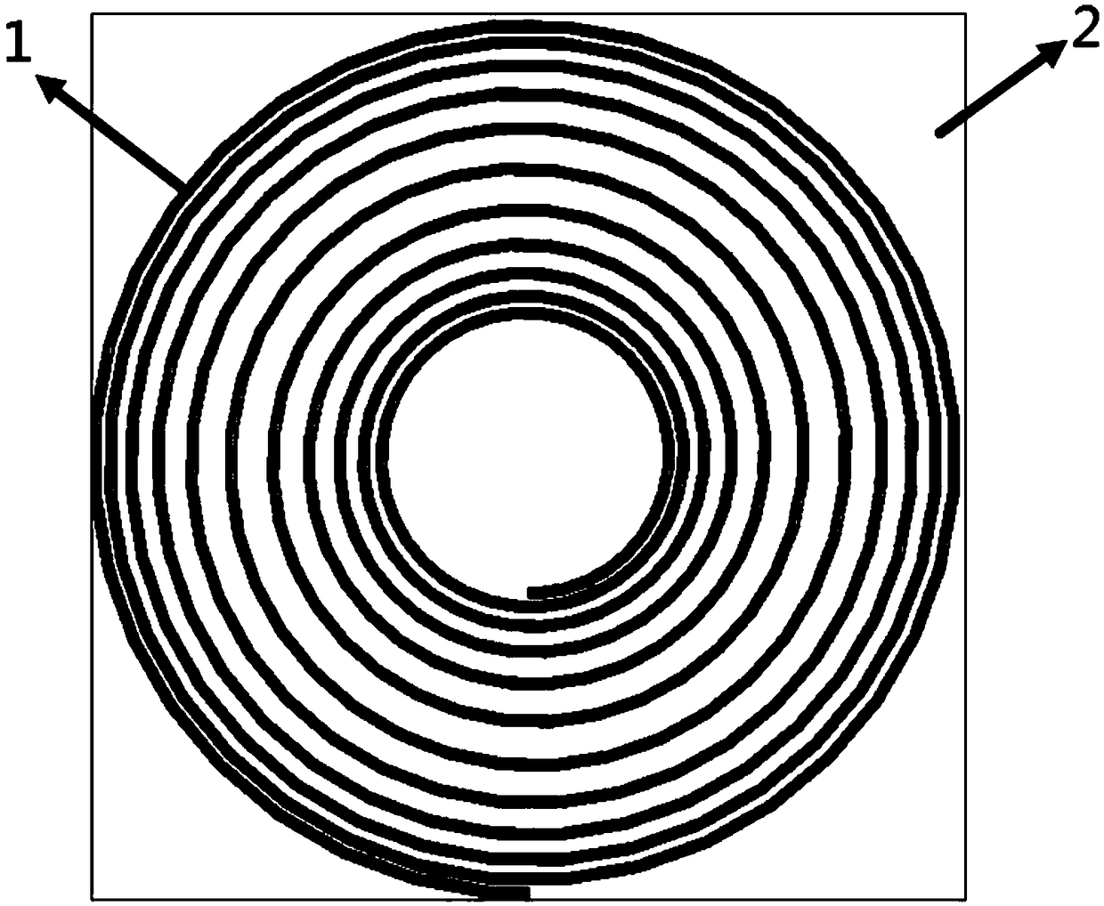
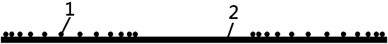
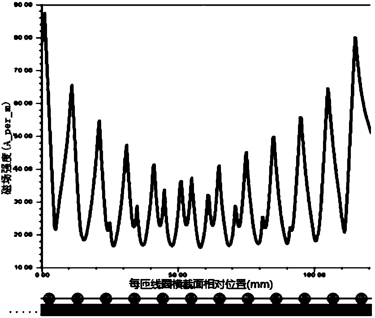
[0023] see figure 1 , figure 2 with image 3 , use a ferrite core whose contact surface can cover the outermost circle of the required coil, take the center point of the core surface as the center, and use an insulated copper wire to coil one circle in a clockwise or counterclockwise direction to obtain the regulation of equal turn spacing A planar spiral coil with inner diameter, outer diameter and number of turns; according to the changing law of the magnetic field strength amplitude of the coil distribution (that is, the magnetic field strength distribution of the coil on the side of the center of the circle presents a trend from large to small and then from small to large), select The position corresponding to the lowest valley of the magnetic field intensity amplitude in the coil is taken as the sparsest point, and with this p...


PUM

PropertyMeasurementUnit
The inside diameter ofaaaaaaaaaa
Outer diameteraaaaaaaaaa

Abstract

The invention provides a variable turn pitch planar helical coil, comprising a magnetic core and a planar helical coil arranged above the magnetic core and coiled by an insulated conductor in a clockwise or counterclockwise direction by turns; The turn spacing of the coil is arranged from close to sparse and then from sparse to close in radial direction from the center of the coil to the outside.As that inner diameter of the plane helical coil does not change the equal turn pitch, outer diameter, On the premise of wire gauge, according to the magnetic field distribution on the coil to changethe dense arrangement of the coil into a planar helical coil with variable turn pitch, the overall magnitude of the magnetic field strength on the coil is reduced, The loss of proximity effect of thecoil is reduced, and the increasing trend of AC internal resistance of the coil is finally alleviated so as to reduce the copper loss of the magnetic coupling structure. At the same time, the magneticfield distribution and offset tolerance characteristics of the spiral coil structure with equal turn pitch are not obviously inferior to those of the spiral coil structure with the same specification(inner diameter, outer diameter, turn number, wire gauge).

Description

technical field [0001] The invention belongs to the technical field of magnetic coupling structure optimization, in particular to a planar spiral coil with variable turn pitch. Background technique [0002] Inductively Power Transfer (IPT) technology is a technology based on the principle of electromagnetic induction to realize non-contact power transmission. The non-contact transformer is a key part of wireless charging in the IPT system. In practical applications, more than 70% of the overall system loss is the non-contact transformer loss, while copper loss (coil loss) and iron loss (magnetic core loss) account for the main part of the non-contact transformer loss. Therefore, in order to reduce the loss, it is necessary to optimize the design of the magnetic coupling structure in the IPT system. [0003] The planar spiral coil is the most typical and widely used coil structure. The magnetic field simulation analysis of the coil wound in the traditional uniform distribut...

Claims


Application Information

Patent Timeline
IPC IPC(8): H01F27/28H01F38/14H02J50/10
CPCH01F27/2823H01F38/14H02J50/10
Inventor 朱国荣胡一豪寿亚涛陆江华李博黎明罗冰洋熊松
Owner WUHAN UNIV OF TECH
Why Eureka
Try Eureka