A street lamp energy-saving control system and a method

An energy-saving control system, energy-saving control technology, applied in the use of semiconductor lamps, electrical components, electroluminescent light sources, etc.

Inactive Publication Date: 2019-01-08
UNILUMIN GRP +1
View PDF4 Cites 6 Cited by
  • Summary
  • Abstract
  • Description
  • Claims
  • Application Information

AI Technical Summary

Problems solved by technology

[0003] The main purpose of the present invention is to propose a street lamp energy saving control system and method, which aims to solve the problem of street lamp energy saving and environmental protection

Method used


Image

  • A street lamp energy-saving control system and a method
  • A street lamp energy-saving control system and a method
  • A street lamp energy-saving control system and a method

Examples


Embodiment 1

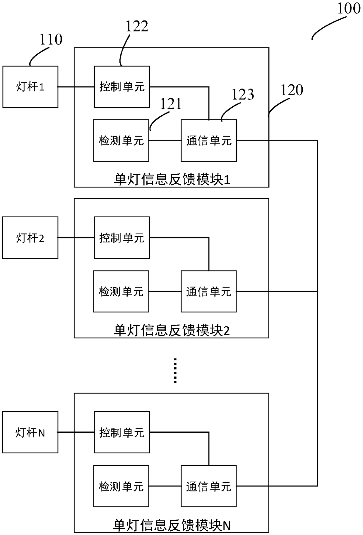
[0020] like figure 1 As shown, Embodiment 1 of the present invention provides a street lamp energy-saving control system 100. The street lamp energy-saving control system 100 includes several light poles 110 and several single-lamp information feedback modules 120 set corresponding to the several light poles 110. Among them, the several light poles 110 They are sequentially arranged beside the road, and each single lamp information feedback module 120 includes a detection unit 121 , a control unit 122 and a communication unit 123 .

[0021] Wherein, the detection unit 121 is mainly used to detect in real time whether there is an object moving on the current road, and obtain the moving direction of the object and the moving speed of the object passing the current light pole. Specifically, the moving object can be a vehicle or a pedestrian, that is, the street lamp energy-saving control system 100 can be applied to a roadway without people or a road with pedestrians. The detect...

Embodiment 2

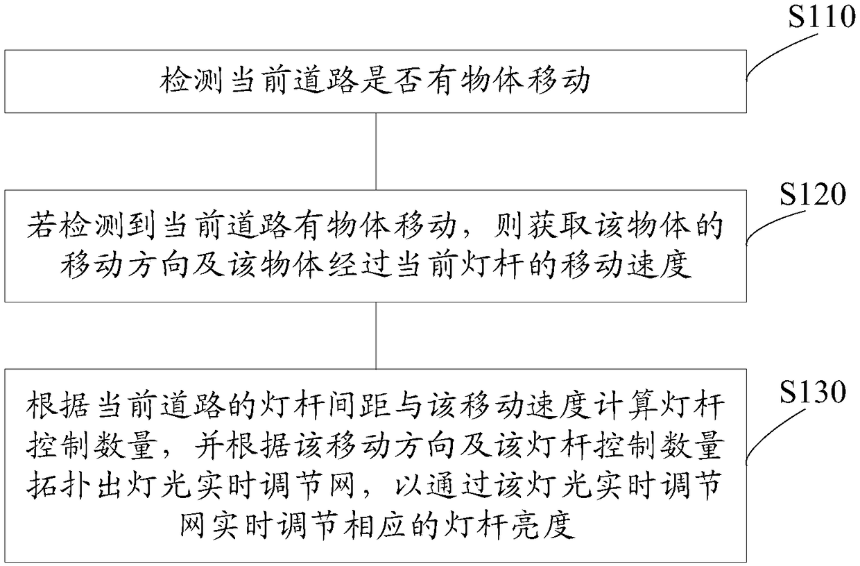
[0027] like image 3 As shown, Embodiment 2 of the present invention also proposes a street lamp energy-saving control method, which is applied to the street lamp energy-saving control system 100 of the above-mentioned Embodiment 1. The street lamp energy-saving control method includes the following steps:

[0028] Step S110: Detect whether there is an object moving on the current road.

[0029] Specifically, this street lamp energy saving control method is mainly based on the following figure 1 The street lamp energy-saving control system 100 shown is implemented. During operation, the street lamp energy-saving control system 100 adjusts the brightness of each lamp pole 110 to a low brightness specified value or does not need to be turned on by default to maximize energy saving. Then, the detection unit 121 of the single lamp information feedback module 120 on each light pole 110 will detect in real time whether there is an object moving on the current road, so as to control t...


PUM


Abstract

The invention discloses a street lamp energy-saving control system and a street lamp energy-saving control method, belonging to the technical field of street lamp energy-saving. The control system comprises a plurality of lamp poles and a plurality of single lamp information feedback modules arranged corresponding to the plurality of lamp poles, A plurality of lamp poles are sequentially arrangedbeside the road, and each single lamp information feedback module comprises a detection unit, which is used for detecting whether an object moves on the current road in real time, and obtaining the moving direction of the object and the moving speed of the object passing through the current lamp pole; The control unit is used for calculating the lamp pole control quantity according to the lamp pole spacing and the moving speed of the current road, and topologically outputting a lamp real-time adjustment network according to the moving direction and the lamp pole control quantity, so as to adjust the brightness of the corresponding lamp pole in real-time through the lamp pole real-time adjustment network. The technical scheme can control the brightness of the corresponding lamp pole according to the actual road situation, so as to achieve the purpose of environmental protection and energy saving.

Description

technical field [0001] The invention relates to the technical field of street lamp energy saving, in particular to a street lamp energy saving control system and method. Background technique [0002] In recent years, LED lights have been widely used in indoor and outdoor lighting due to their advantages of long life, low energy consumption, and environmental protection. At present, LED street lamps on the market generally use methods such as timing switches and intelligent dimming to further save energy. However, in the actual use process, there will be many uncontrollable factors. When high-brightness lighting is required, the brightness cannot be adjusted in time, which poses a safety hazard. It is not environmentally friendly. Contents of the invention [0003] The main purpose of the present invention is to provide a street lamp energy saving control system and method, which aims to solve the problem of energy saving and environmental protection of street lamps. [...

Claims


Application Information

Patent Timeline
Patent Type & Authority Applications(China)
IPC IPC(8): H05B33/08H05B44/00
CPCH05B45/14H05B45/50Y02B20/30
Inventor 张德峰路振高苑文波袁小佩周晴李江海
Owner UNILUMIN GRP
Why Eureka
Try Eureka