Trajectory height pre-measuring compensation system

A compensation system and trajectory technology, applied in auxiliary devices, coatings, laser welding equipment, etc., can solve problems such as increasing the time required for processing, impacting the processing head, and damage to the workpiece

Pending Publication Date: 2019-01-11
新代科技(苏州)有限公司
View PDF0 Cites 3 Cited by
  • Summary
  • Abstract
  • Description
  • Claims
  • Application Information

AI Technical Summary

Problems solved by technology

[0004] In addition, when the shape of the part to be processed on the workpiece is multiple line segments or continuous processing is required, the processing path information of the workpiece, such as the coordinates of the turning point of the processing path, needs to be input to the processing machine first, and the processing machine moves again The height measurement probe measures the height at these turning points, and then moves the processing head along the processing path to perform processing operations. However, this method only measures the height at the turning points on each processing path. When there is a height change in the processing path, the processing head is very likely to hit the workpiece while moving along the processing path, causing damage to the processing head or the workpiece
In order to prevent the occurrence of the above situation, the processing machine can also be designed to first control the height measuring probe to measure the height of the overall processing path along the processing path, then compensate the height measurement result to the processing path information to correct the processing height, and finally process The head then processes the workpiece or semi-finished product along the corrected processing path. However, it needs to scan the processing path twice, which will greatly increase the time required for processing.

Method used


Image

  • Trajectory height pre-measuring compensation system
  • Trajectory height pre-measuring compensation system
  • Trajectory height pre-measuring compensation system

Examples


Embodiment Construction

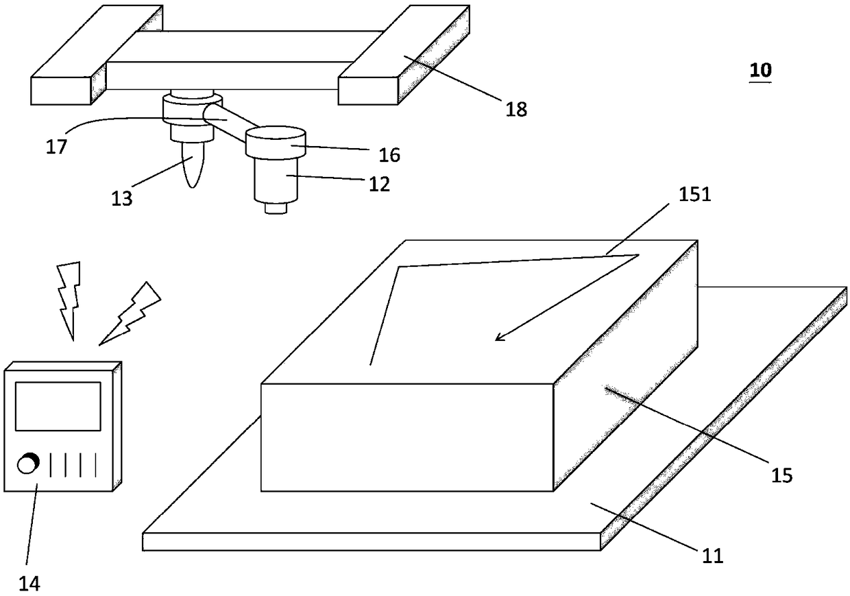
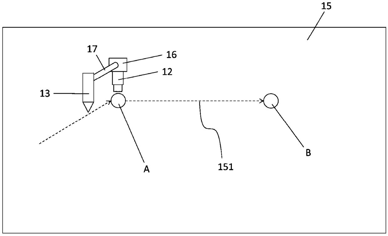
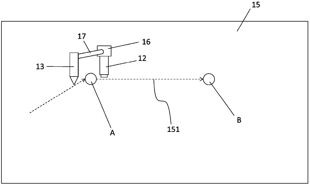
[0041]The following will clearly and completely describe the technical solutions in the embodiments of the present invention with reference to the accompanying drawings in the embodiments of the present invention. Obviously, the described embodiments are only some, not all, embodiments of the present invention. The components of the embodiments of the invention generally described and illustrated in the figures herein may be arranged and designed in a variety of different configurations. Accordingly, the following detailed description of the embodiments of the invention provided in the accompanying drawings is not intended to limit the scope of the claimed invention, but merely represents selected embodiments of the invention. Based on the embodiments of the present invention, all other embodiments obtained by those skilled in the art without making creative efforts belong to the protection scope of the present invention.

[0042] It should be noted that like numerals and lett...


PUM


Abstract

The invention relates to a trajectory height pre-measuring compensation system, which comprises a workpiece platform, a height-measuring probe unit, a machining head and a shaft control unit. The workpiece platform is used for bearing a to-be-machined workpiece. The height-measuring probe unit is arranged on a bearing platform and used for measuring the plane height of the to-be-machined workpiece. The bearing platform is connected to the machining head in a pivoted mode through a link mechanism, and the link mechanism can rotate along the machining head. The axial control unit is used for setting one or more mechanism parameters of the link mechanism and the bearing platform, controlling the height-measuring probe unit to pre-measure the plane height of the to-be-machined workpiece on themachining path of the to-be-machined workpiece, and controlling the machining head to adjust the machining height and the rotation angle according to the plane height, pre-measured by the height-measuring probe unit, of the to-be-machined workpiece on the machining path so as to machine the to-be-machined workpiece on the machining path. The height of the machined workpiece is measured along themachining trajectory, then the to-be-machined workpiece is machined, thus the machining time is shortened, and the impact possibility of the machining head and the to-be-machined workpiece is decreased.

Description

technical field [0001] The invention relates to a track pre-measurement height compensation system, in particular to a pre-measurement compensation and track pre-measurement system that can scan the height of the workpiece along the processing path of the workpiece to be processed and then process the workpiece to reduce the processing time. Altimeter compensation system. Background technique [0002] In modern industry, in order to perform more precise operations on products such as dispensing, laser cutting, etc., processing machines are indispensable equipment in the factory. Since the workpiece or semi-finished product may have poor consistency due to various factors in the manufacturing process during mass production, the surface of the workpiece or semi-finished product may have uneven flatness. Semi-finished products are processed, and a height measuring probe will be installed next to the processing head of the existing processing machine. This height measuring prob...

Claims


Application Information

Patent Timeline
IPC IPC(8): B23K26/70B23K37/00B23K37/02B05C5/02B05C11/10
CPCB05C5/02B05C11/10B23K26/70B23K37/00B23K37/02
Inventor 蔡侑庭林仪婷沈彦廷
Owner 新代科技(苏州)有限公司
Why Eureka
Try Eureka