Dam maintenance ladder

A technology of dams and ladder rods, which is applied to ladders, electrical components, mechanical equipment, etc., can solve the problems of short service life of equipment, easy brittleness of equipment materials, and loss of internal temperature, so as to improve the quality of protection, protect equipment safety and The safety of personnel use and the effect of ensuring the effect

Inactive Publication Date: 2021-03-16
陈斌
View PDF1 Cites 0 Cited by
  • Summary
  • Abstract
  • Description
  • Claims
  • Application Information

AI Technical Summary

Problems solved by technology

[0005] Aiming at the deficiencies of the prior art, the present invention provides a dam maintenance ladder, which can solve the problem that during the use of the existing dam maintenance ladder, the surface water flow flows, which easily drives debris in the water to hit the ladder and damage the internal electronic components. Devices, resulting in equipment damage, and the continuous flow of water causes rapid loss of internal temperature, resulting in low equipment temperature, easy embrittlement of equipment materials, resulting in a short service life of the equipment

Method used


Image

  • Dam maintenance ladder
  • Dam maintenance ladder
  • Dam maintenance ladder

Examples


Embodiment 1

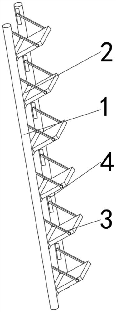
[0040] see Figure 1-2 , the present invention provides a technical solution: a dam maintenance ladder, including a ladder bar 1, a mounting shaft 2 is movably connected to the side of the ladder bar 1 close to each other, a pedal 3 is movably connected to the right side of the outer surface of the mounting shaft 2, and the ladder bar 1 There is a mounting groove 4 on one side close to each other and above the mounting shaft 2;

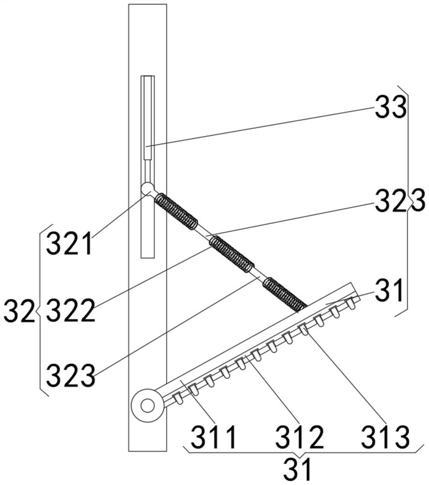
[0041] The pedal 3 includes a main board 31, the front and back of the main board 31 and the side away from the installation shaft 2 are movably connected with an adjustment rod 32, and the end of the adjustment rod 32 away from the main board 31 is movably connected with a telescopic rod 33, and the end of the telescopic rod 33 is far away from the adjustment rod 32 It is movably connected with the installation groove 4.

[0042] The main board 31 includes a plate body 311. The side of the plate body 311 away from the ladder bar 1 is provided with a...

Embodiment 2

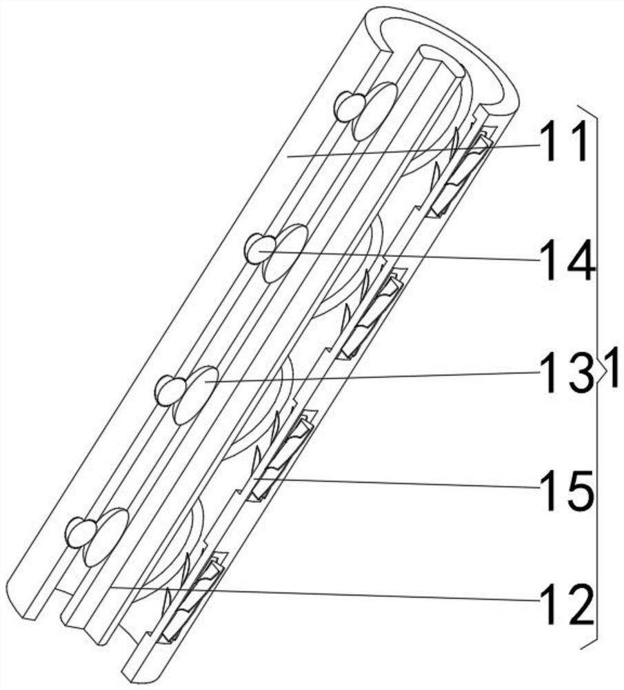
[0047] see Figure 1-5 , on the basis of Embodiment 1, the present invention provides a technical solution: the ladder rod 1 includes a rod barrel 11, and the inner surface of the inner cavity of the rod barrel 11 is fixedly connected with a rebound mechanism 12 on the side close to the installation shaft 2, and the rebound mechanism 12 The side away from the installation shaft 2 is movably connected with a buffer ellipse 13, the outer surface of the rod barrel 11 is fixedly connected with an anti-collision mechanism 14 at the side far from the installation shaft 2 and at the position of the buffer ellipse 13, and the outer surface of the rod barrel 11 is front A guide vane 15 is fixedly connected to the position of the rebound mechanism 12 .

[0048] The buffer ellipse 13 is flexibly connected to the anti-collision mechanism 14 on the side away from the rebound mechanism 12. The guide vane 15 penetrates the rod barrel 11 and extends to the inner cavity of the rod barrel 11. T...


PUM


Abstract

The invention discloses a dam maintenance ladder, and relates to the technical field of hydraulic engineering. The dam maintenance ladder comprises ladder rods, mounting shafts are movably connected to the sides, close to each other, of the ladder rods, pedals are movably connected to the right sides of the outer surfaces of the mounting shafts, and mounting grooves are formed in the sides, closeto each other and located above the mounting shafts, of the ladder rods. Each pedal comprises a main plate, adjusting rods are movably connected to the sides, away from the mounting shafts, of the front faces and the back faces of the main plates, telescopic rods are movably connected to the ends, away from the main plates, of the adjusting rods, and the ends, away from the adjusting rods, of thetelescopic rods are movably connected with the mounting grooves. The adjusting rods comprise mounting bolt rods, electromagnetic reinforcing rods are fixedly connected to the sides, close to each other, of the mounting bolt rods, and elastic protection rods are fixedly connected to the ends, away from the mounting bolt rods, of the electromagnetic reinforcing rods. The whole structure is simple, self-resetting is realized, the occupied space is saved, the space utilization rate is improved, the collision possibility is reduced, and the self-safety is protected.

Description

technical field [0001] The invention relates to the technical field of water conservancy, in particular to a dam maintenance ladder. Background technique [0002] With the rapid development of my country's economy and urban infrastructure, more and more water conservancy maintenance ladders are used in industry, but the water conservancy maintenance ladders used in modern industry only pay attention to the waterproof and sunscreen performance of the materials used. It does not pay attention to functions such as convenience and safety when it is working. [0003] According to Chinese patent CN107368021A, when the equipment starts to work, the equipment will vibrate, and the top of the base is connected with the bottom of the support frame through the shock absorber, which can not only reduce the vibration generated by the equipment through the shock absorber, but also fix the base , to ensure its stability and the safety of personnel work; when the load of the fixed table exc...

Claims


Application Information

Patent Timeline
Patent Type & Authority Applications(China)
IPC IPC(8): E06C1/08E06C1/387E06C7/00E06C7/08F03B13/00H02N11/00H02N1/04
CPCE06C1/08E06C1/387E06C7/00E06C7/08F03B13/00H02N1/04H02N11/002
Inventor 陈斌
Owner 陈斌
Why Eureka
Try Eureka