Eureka AIR delivers breakthrough ideas for toughest innovation challenges, trusted by R&D personnel around the world.

Metal sheet processing equipment and operation method thereof

A technology of processing equipment and operation method, which is applied in the direction of metal processing equipment, metal processing, metal processing machinery parts, etc., can solve the problems of difficult to achieve high-intensity operations, difficult to guarantee the quality of products, and low efficiency of manual operation, etc., and achieve compact structure, Simple mechanism and cost saving effect

Inactive Publication Date: 2019-01-11
何杨波
View PDF0 Cites 2 Cited by
  • Summary
  • Abstract
  • Description
  • Claims
  • Application Information

AI Technical Summary

Problems solved by technology

[0002] In the context of the current industrial development towards automation, traditional small-scale metal sheet stamping still uses manual processing, which is inefficient and costly, difficult to achieve high-intensity operations, and prone to production safety accidents, because manual operations are difficult to achieve Standardization, it is difficult to guarantee the quality of the product, it is difficult to realize automation, there are major disadvantages, and it needs to be improved

Method used

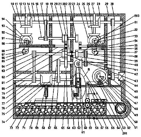

Image

  • Metal sheet processing equipment and operation method thereof
  • Metal sheet processing equipment and operation method thereof
  • Metal sheet processing equipment and operation method thereof

Examples


Embodiment Construction

[0024] All features disclosed in this specification, or steps in all methods or processes disclosed, may be combined in any manner, except for mutually exclusive features and / or steps.

[0025] Any feature disclosed in this specification (including any appended claims, abstract and drawings), unless expressly stated otherwise, may be replaced by alternative features which are equivalent or serve a similar purpose. That is, unless expressly stated otherwise, each feature is one example only of a series of equivalent or similar features.

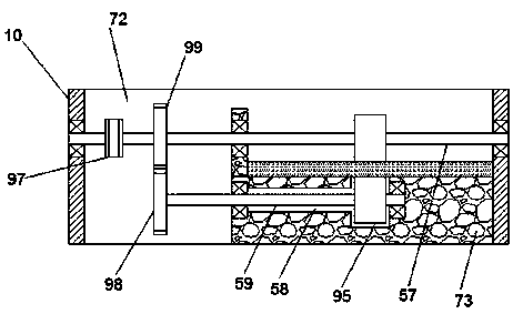
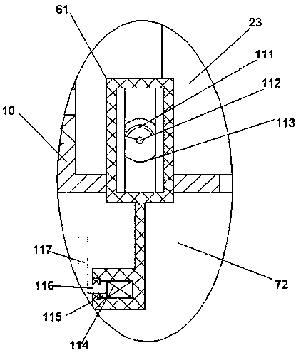
[0026] Such as Figure 1-3 As shown, a kind of sheet metal processing equipment and its operation method of the device of the present invention include a main box 10 and a cutting device arranged in the main box 10, the main box 10 is provided with a first rotating chamber 12, The main box body 10 is provided with a second rotating chamber 19 on the right side of the first rotating chamber 12, and the main box body 10 is provided with a third...


PUM


Abstract

The invention discloses metal sheet processing equipment and an operation method thereof. The metal sheet processing equipment comprises a main box body and a cutting device arranged in the main box body. A first rotating cavity is arranged in the main box body, and a second rotating cavity located on the right side of the first rotating cavity is arranged in the main box body. A third rotating cavity located on the right side of the second rotating cavity is arranged in the main box body, and a motor cavity located on the right side of the third rotating cavity is arranged in the main box body. A fourth rotating cavity located on the lower side of the first rotating cavity is arranged in the main box body, and a stamping cavity which is located on the lower side of the fourth rotating cavity and provided with a forward opening is arranged in the main box body. A first rotating shaft is rotatably arranged on the top wall of the first rotating cavity, and a first bevel gear is fixedly arranged on the first rotating shaft. A fourteenth bevel gear is fixedly arranged at the lower end of the first rotating shaft, a second rotating shaft is arranged on the left wall of the first rotating cavity in a rotating mode, and the right end of the second rotating shaft is rotatably connected with the right wall of the motor cavity through the second rotating cavity, the third rotating cavity, and the motor cavity.

Description

technical field [0001] The invention relates to the field of industrial technology, in particular to a sheet metal processing equipment and its operating method. Background technique [0002] In the context of the current industrial development towards automation, traditional small-scale metal sheet stamping still uses manual processing, which is inefficient and costly, difficult to achieve high-intensity operations, and prone to production safety accidents, because manual operations are difficult to achieve Standardization, it is difficult to guarantee the quality of the product, it is difficult to realize the automation, there are big disadvantages, and it needs to be improved. Contents of the invention [0003] Aiming at the deficiencies of the above technologies, the present invention proposes a thin metal plate processing equipment and its operation method. [0004] The invention relates to a metal sheet processing equipment and its operation method, comprising a mai...

Claims


Application Information

Patent Timeline
IPC IPC(8): B23P23/04B23D19/00B21D22/02B30B1/24B23Q7/02B23Q7/05B23Q5/38
CPCB23P23/04B21D22/02B23D19/00B23Q5/385B23Q7/02B23Q7/05B30B1/24
Inventor 何杨波
Owner 何杨波
Why Eureka
Eureka Blog
Learn More