Supercharge Your Innovation With Domain-Expert AI Agents!

Side pushing self-lock device

A technology of self-locking device and self-locking clamp, which is applied in the direction of positioning device, clamping, support, etc., can solve the problems of complex positioning, easy to be damaged by the clamp, and slippage of the workpiece, and achieve the effect of simple positioning and stable clamping

Pending Publication Date: 2019-01-11
伯恩高新科技(惠州)有限公司
View PDF0 Cites 0 Cited by
  • Summary
  • Abstract
  • Description
  • Claims
  • Application Information

AI Technical Summary

Problems solved by technology

[0003] In view of the deficiencies in the prior art, the purpose of the present invention is to provide a side push self-locking device to solve the shortcomings of the prior art in that the workpiece slips, is easily damaged by the fixture, and the positioning is complicated

Method used


Image

  • Side pushing self-lock device
  • Side pushing self-lock device
  • Side pushing self-lock device

Examples


Embodiment Construction

[0019] The specific embodiments of the present invention will be further described below in conjunction with the accompanying drawings. It should be noted here that the description of the following embodiments is used to help understand the invention, but does not constitute a limitation to the invention.

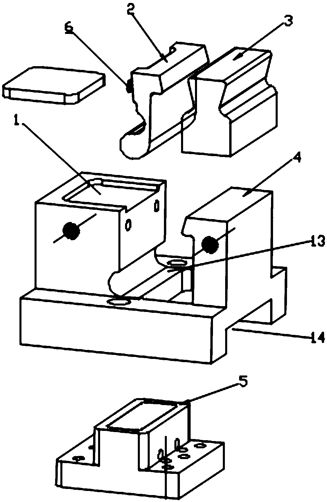
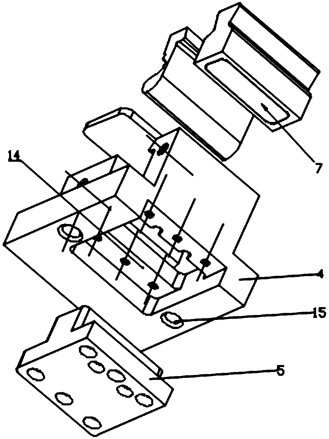
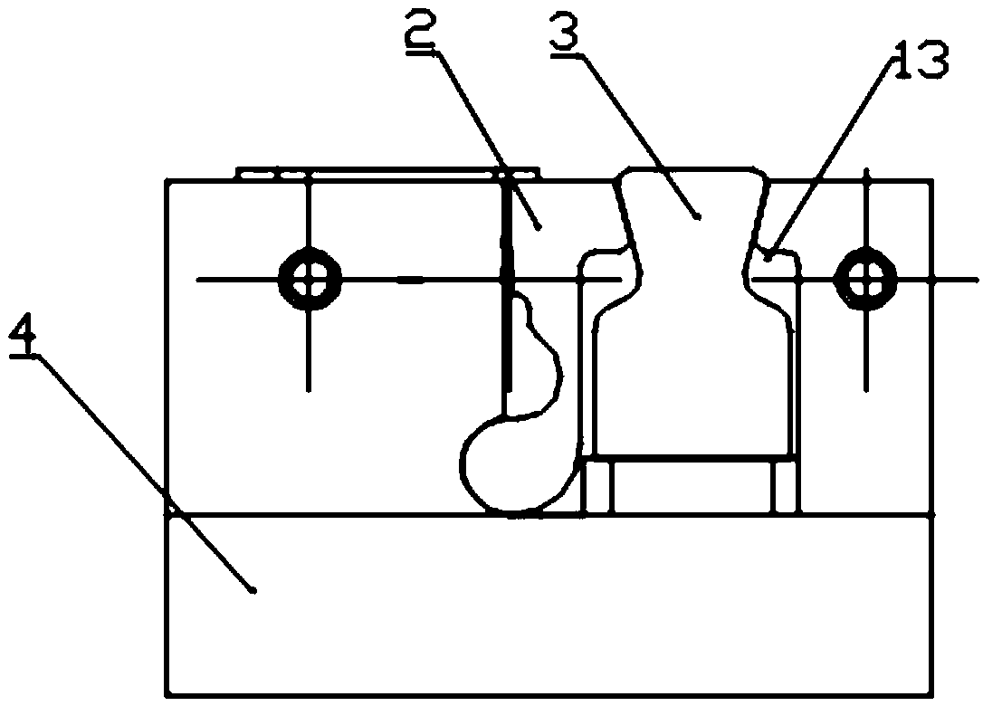
[0020] figure 1 , figure 2 A side push self-locking device of the present invention is shown, which includes a side push self-locking fixture; the side push self-locking fixture includes an upper mold base 4, and the upper mold base 4 is provided with 3 grooves, which are respectively: opened in The inner side of the upper die base 4 and the magnetic groove 13 at the bottom of the upper die base 4; the bottom groove 14 at the bottom of the upper die base 4; the processing groove 1 above the upper die base 4 and bordering on the magnetic groove 13; the magnetic groove 13 A side push block 2 and a convex slide block 3 are arranged inside, the side push block 2 and the conv...


PUM


Abstract

The invention relates to a side pushing self-lock device which comprises a side pushing self-lock. The side pushing self-lock comprises an upper mold base. Three grooves are formed in the upper mold a magnetic groove formed in the inner side of the upper mold base and penetrating the bottom of the upper mold base, a bottom groove formed in the bottom of the upper mold base and a processing groove formed above the upper mold base and neighboring the magnetic groove. A side pushing block and a convex slide block are arranged in the magnetic groove, the side pushing block and the convex slide block are placed left and right and the side pushing block is attached to a bevel of the convex slide block, a spring is arranged between the side wall of the magnetic groove and the side pushing block, and a neodymium magnet is fixedly arranged at the bottom of the convex slide block; an electromagnetic block is embedded into the bottom groove; the electromagnetic block is connected to a conducting device; the whole device clamps automatically and stably without generating a clamping deviation.

Description

technical field [0001] The invention relates to the field of self-locking clamps, in particular to a side push self-locking device. Background technique [0002] Fixture refers to the device used to fix the processing object in the process of mechanical manufacturing so that it occupies the correct position to accept construction or inspection. In a broad sense, any process in the process, the device used to install the workpiece quickly, conveniently and safely, can be called a fixture. Fixtures are usually composed of positioning elements, clamping devices, guiding elements, indexing devices, connecting elements, and clamping bodies. Machine tool fixtures are the most common. When the workpiece is processed by the machine tool, in order to make the surface of the workpiece meet the technical requirements of the size, geometric shape and mutual position accuracy with other surfaces specified in the drawing, the workpiece must be installed (positioned) and clamped firmly be...

Claims


Application Information

Patent Timeline
Patent Type & Authority Applications(China)
IPC IPC(8): B23Q3/06B23Q3/08
CPCB23Q3/06B23Q3/08
Inventor 张攀冯银银
Owner 伯恩高新科技(惠州)有限公司
Features
  • R&D
  • Intellectual Property
  • Life Sciences
  • Materials
  • Tech Scout
  • Unparalleled Data Quality
  • Higher Quality Content
  • 60% Fewer Hallucinations
Learn More