
Constraint device of engine shaft part

A technology of engine shaft and restraint device, which is used in metal processing mechanical parts, positioning devices, clamping and other directions to achieve the effect that the coaxiality is easy to ensure

Active Publication Date: 2019-01-11
CHENGDU ZHIRONG ZHICHUANG INTPROP MANAGEMENT CO LTD
View PDF6 Cites 0 Cited by
  • Summary
  • Abstract
  • Description
  • Claims
  • Application Information

AI Technical Summary

Problems solved by technology

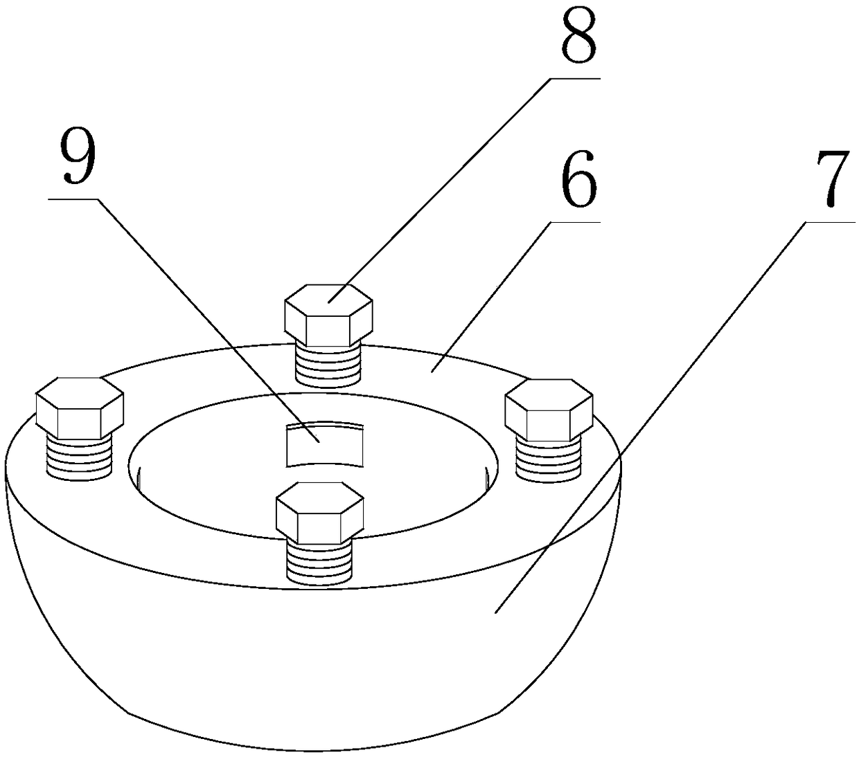
[0006] In view of the above problems, the present invention provides a restraint device for engine shaft parts to solve the problem through the following technical points: a restraint device for engine shaft parts, including a hoop for clamping shaft parts, on the hoop There is a through hole for clamping shaft parts, the end face of one end of the hoop is flat, and a plurality of clamping devices are installed on the hoop, and the clamping devices are evenly distributed in a ring relative to the axis of the through hole , the clamping device realizes the position fixation of the hoop on the axis of the shaft part by applying pressure to the shaft part, and the clamping device includes a pressure plate, a slider, an elastic sheet and a first bolt; the middle part of the elastic sheet A deformation section in the shape of a bridge arch is also provided;

Method used


Image

  • Constraint device of engine shaft part
  • Constraint device of engine shaft part
  • Constraint device of engine shaft part

Examples


Embodiment 1

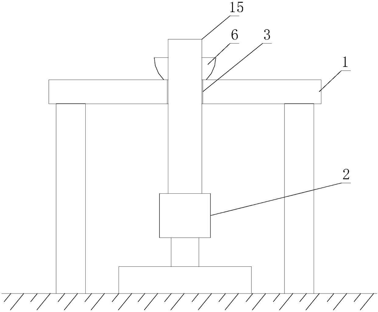
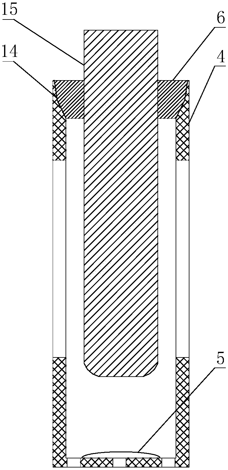
[0036] Such as Figure 1 to Figure 5 , a constraining device for engine shaft parts, including a hoop 6 for clamping shaft parts 15, said hoop 6 is provided with a through hole for clamping shaft parts 15, and one end of said hoop 6 The end face is flat, and a plurality of clamping devices are installed on the hoop 6, and the clamping devices are evenly distributed in a circle relative to the axis of the through hole. 6. The position on the axis of the shaft part 15 is fixed. The clamping device includes a pressure plate 9, a slider 10, an elastic piece 11 and a first bolt 8; part;

[0037] The hoop 6 is provided with a tunnel for installing a clamping device, and the tunnel is connected to the through hole on the hoop 6, and the slider 10 is partially located in the tunnel, and the slider 10 can move along the channel sliding;

[0038] The pressing plate 9 is fixed on one end of the slider 10 close to the through hole, one end of the elastic sheet 11 is fixed on the end of...

Embodiment 2

[0043] Such as Figure 1 to Figure 5 , this embodiment is further limited on the basis of Embodiment 1: as an integrated design, it also includes a workbench 1 for completing the connection between the hoop 6 and the shaft parts 15, and the upper surface of the workbench 1 is plane, the workbench 1 is also provided with a through-hole 3 passing through the upper and lower surfaces of the workbench 1, and the axis of the through-hole 3 is perpendicular to the upper surface of the workbench 1;

[0044] It also includes a jacking mechanism 2 arranged on the lower side of the workbench 1 and facing the through hole 3. The top of the jacking mechanism 2 is a supporting surface for supporting shaft parts 15. The height of the supporting surface is adjustable. When this solution is in use, it is set that the plane is installed as a horizontal plane, so that the shaft part 15 can be inserted into the through hole 3 from the upper end of the through hole 3 and the lower end is support...


PUM


Abstract

The invention discloses a constraint device of an engine shaft part, The restraining device of the engine shaft part comprises a hoop ring, a through hole is formed in the hoop ring, an end face of one end of the hoop ring is a plane, and the hoop ring is provided with a plurality of clamping devices; each clamping device comprises a pressing plate, a sliding block, an elastic piece and a first bolt, wherein deformation sections are further arranged in the middles of the elastic pieces, a hole channel is formed in the hoop ring, the sliding blocks are partially located in the hole channel, andthe sliding blocks can slide along the hole channel; the pressing plate is fixed at one ends, close to the through hole, of the sliding blocks, one ends of the elastic pieces are fixed to one ends, far away from the through hole, of the sliding blocks, and the other ends of the elastic pieces are fixedly connected with the hoop ring; and a first bolt is in threaded connection with the hoop ring,one end of the first bolt extends into the hole channel, and the end part of the first bolt extending into the hole channel acts on outer convex sides of the deformation sections. According to the constraint device, the relation between the axis of the shaft part and the axis of the constraint device can be conveniently controlled.

Description

technical field [0001] The invention relates to the technical field of automobile and motorcycle engine manufacturing, in particular to a constraining device for engine shaft parts. Background technique [0002] In the prior art, along with the development of my country's economy, society's demand for automobiles and motorcycles and the amount of automobiles and motorcycles on the market gradually increase. At the same time, my country's automobile manufacturing technology has also developed rapidly. Engines for automobiles and motorcycles generally include crankshafts, connecting rods, pistons, cylinders, intake ports, intake valves, fuel injectors, exhaust valves, exhaust ports and housings. Among these parts, there are shaft parts on the connecting rod, piston, intake valve and exhaust valve. [0003] For the manufacture of the above-mentioned shaft parts, the existing manufacturing process includes related dimension forming process, welding process, electroplating proc...

Claims


Application Information

Patent Timeline
Patent Type & Authority Applications(China)
IPC IPC(8): B23Q3/06
CPCB23Q3/064
Inventor 胡明容
Owner CHENGDU ZHIRONG ZHICHUANG INTPROP MANAGEMENT CO LTD
Learn More