
Fan motor and eccentric fan

A technology of electric motors and fans, which is applied in the direction of electric components, machines/engines, liquid fuel engines, etc. It can solve the problems of troublesome assembly of fan motors, poor running stability, and poor assembly accuracy, and achieve low noise, stable operation, and simple assembly Effect

Pending Publication Date: 2019-09-10
宋振明
View PDF0 Cites 0 Cited by
  • Summary
  • Abstract
  • Description
  • Claims
  • Application Information

AI Technical Summary

Problems solved by technology

[0004] Aiming at the defects in the prior art, the present invention provides a fan motor to solve the problems of troublesome assembly, poor assembly accuracy, poor running stability and high running noise of the existing fan motor

Method used


Image

  • Fan motor and eccentric fan
  • Fan motor and eccentric fan
  • Fan motor and eccentric fan

Examples

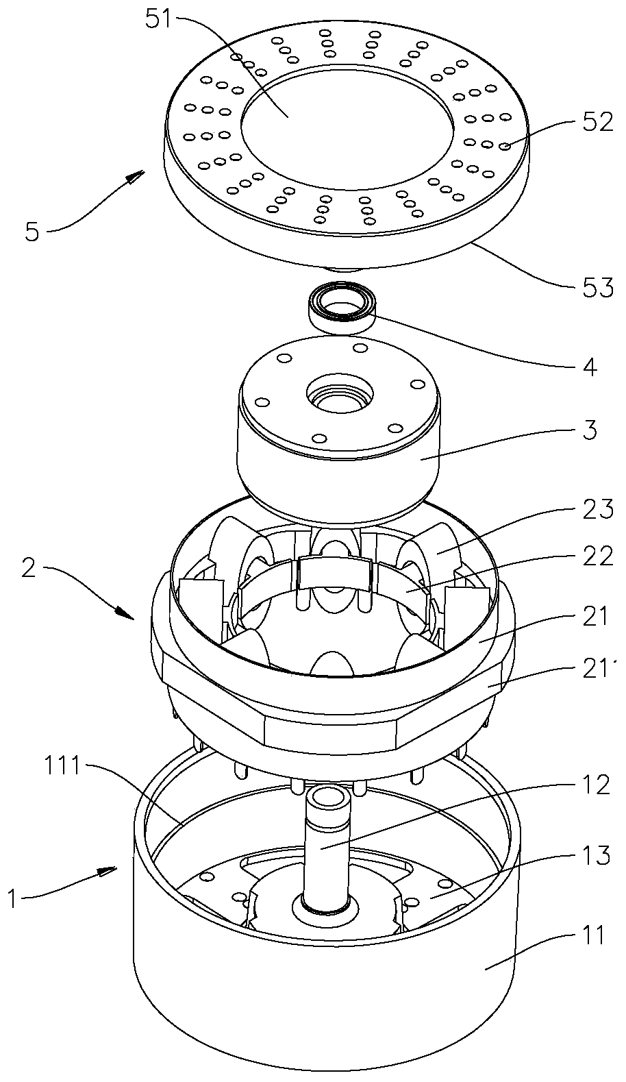
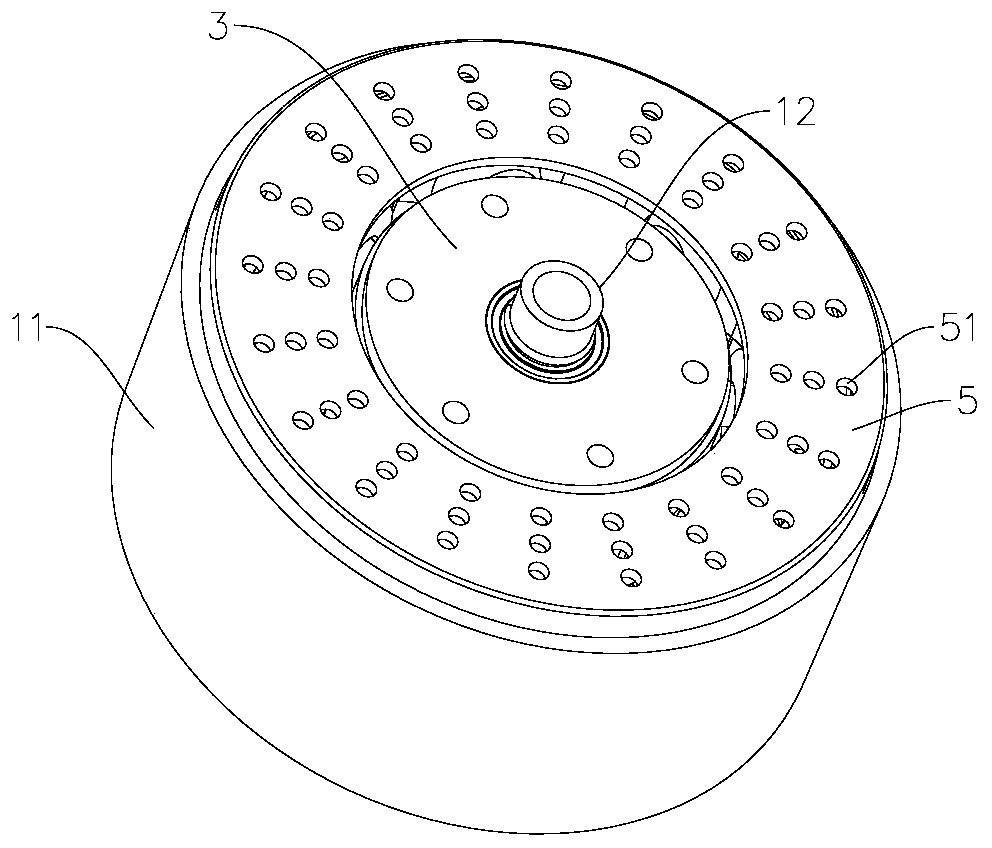
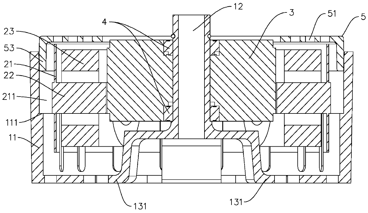

Embodiment Construction

[0023] Embodiments of the technical solutions of the present invention will be described in detail below in conjunction with the accompanying drawings. The following examples are only used to illustrate the technical solution of the present invention more clearly, and therefore are only examples, and should not be used to limit the scope of protection of this patent.

[0024] like Figure 1-Figure 4 As shown, the embodiment of the present invention provides a fan motor, the fan motor electric fan, tower fan, air conditioner fan and so on.

[0025] The fan motor includes a fixed seat 1, a stator assembly 2 and a rotor 3, the fixed seat 1 includes an annular casing 11, a rotor shaft 12 coaxially arranged in the annular casing 11, and one end connected to the annular casing 11 and the rotor shaft 12 for fixing The connecting portion 13 of the rotor shaft 12 , the rotor 3 is coaxially mounted on the rotor shaft 12 through the bearing 4 , and the stator assembly 2 is arranged arou...


PUM


Abstract

The invention discloses a fan motor. The fan motor comprises a fixed seat, a rotor and a stator assembly, wherein the fixed seat comprises an annular shell, a rotor shaft and a connection part, wherein the rotor shaft is coaxially arranged in the annular shell, the connection part is connected to one end of the annular shell and one end of the rotor shaft and is used for fixing the rotor shaft, the rotor is coaxially arranged on the rotor shaft by a bearing, the stator assembly is arranged in a way encircling the periphery of the rotor and is fixed on an inner circumferential wall of the annular shell. By the fan motor, the problems that an existing fan motor is trouble to assemble and is poor in assembly accuracy, poor in running stability and large in running noise are solved. The invention also discloses an eccentric fan comprising the fan motor.

Description

technical field [0001] The invention relates to the technical field of fans, in particular to a fan motor and a centrifugal fan. Background technique [0002] The fan motor is the power mechanism of the fan, and its function is to provide power for the rotation of the fan blade. The existing fan motor generally includes a shell, a stator, a rotor and a rotor shaft. The bottom of the rotor shaft is riveted with a copper ring structure, and then a metal gasket is used to Cooperate with the bottom of the rotor shaft, which has the problems of troublesome assembly, poor assembly accuracy, difficulty in controlling the concentricity of the rotor shaft and the stator, and, due to the fit gap between the rotor shaft and the copper ring, the rotor shaft will swing radially during operation , the stability of operation is poor, and at the same time, the rotor shaft will move axially, and friction will be generated between the bottom end of the rotor shaft and the gasket, resulting in...

Claims


Application Information

Patent Timeline
IPC IPC(8): H02K1/28H02K5/04H02K5/20F04D25/08F04D17/16F04D29/62
CPCH02K1/28H02K5/04H02K5/20F04D25/08F04D17/16F04D29/626
Inventor 宋振明
Owner 宋振明
Learn More