Intelligent vibrating method for high-strength concrete member

A concrete and high-strength technology, applied in auxiliary molding equipment, ceramic molding machines, manufacturing tools, etc., can solve problems such as increased operational difficulty, poor fluidity of concrete materials, and missed vibration, so as to improve the quality of vibration and shorten the time of vibration Time, the effect of reducing the difficulty of operation

Active Publication Date: 2019-01-11
上海电气研砼(徐州)重工科技有限公司
View PDF5 Cites 11 Cited by
  • Summary
  • Abstract
  • Description
  • Claims
  • Application Information

AI Technical Summary

Problems solved by technology

[0002] In the production process of high-strength concrete components, it needs to be compacted and vibrated after the concrete is placed. The concrete materials used in high-strength concrete components are mainly high-pressure, high-tensile, high-elastic modulus, and tensile strain hardening. The characteristic is that it contains a large amount of steel fibers. In order to ensure the self-distribution of steel fibers, the technical requirements are that the steel fibers must not sink to the bottom. Therefore, the existing component vibration platform cannot be used for concrete vibration, and only manual vibration can be used; however, the concrete The fluidity of the material is extremely poor, and the initial setting time is extremely short (the initial setting starts in 30 minutes), and manual vibration cannot guarantee that the concrete placed in such a short period of time can be vibrated, so mechanical vibrating rods can be considered for vibrating
[0003] In the actual vibration process, the structural fo

Method used


Image

  • Intelligent vibrating method for high-strength concrete member
  • Intelligent vibrating method for high-strength concrete member
  • Intelligent vibrating method for high-strength concrete member

Examples


Embodiment Construction

[0032] The present invention will be described in further detail below in conjunction with the accompanying drawings.

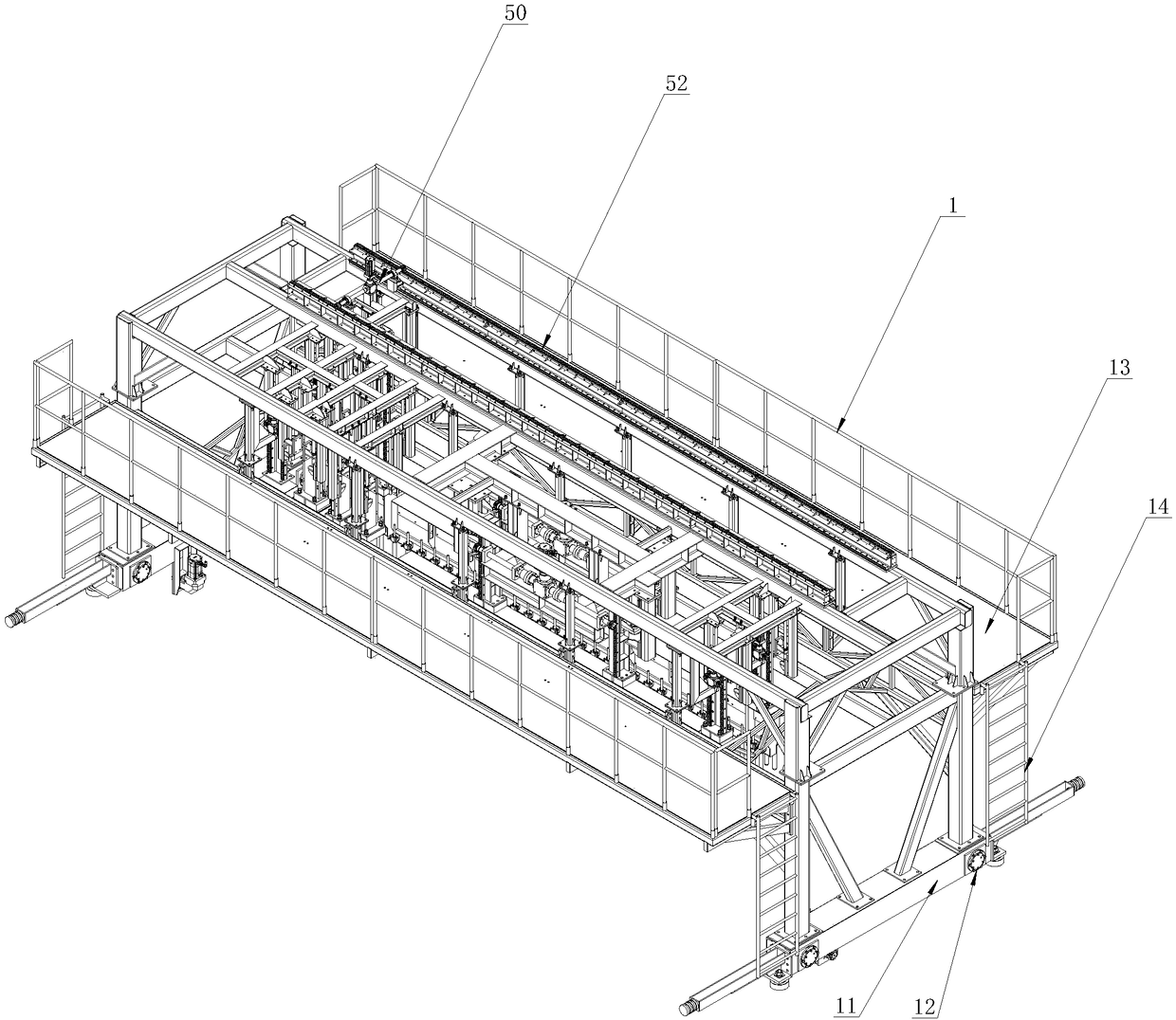
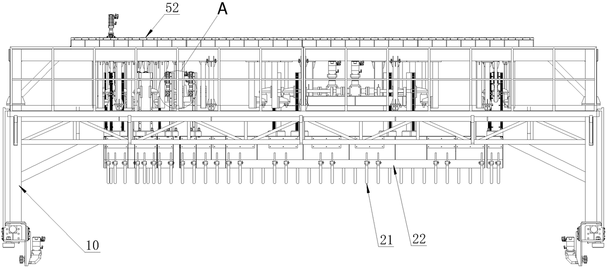
[0033] As shown in the figure, the concrete vibrating equipment used in the present invention includes a vehicle frame 1. The vehicle frame 1 includes a door frame body 10 and a vehicle frame traveling mechanism installed on the door frame body 10. The vehicle frame is provided with a PLC control system; the gantry body 10 is provided side by side along its width direction with an end tenon vibrator 20 , a middle vibrator 30 and a vibrator 40 ;

[0034] The tenon vibrator 20 includes a plurality of tenon vibrating rods 21 suspended at intervals along the length direction of the door frame body 10, and the tenon vibrating rods 21 are driven to move up and down by the tenon lifting system;

[0035] The central vibrator 30 includes a plurality of central vibrating rod groups 31 suspended at intervals along the length direction of the door frame body 10, wherein ...


PUM


Abstract

The invention discloses an intelligent vibrating method for a high-strength concrete member. Through a PLC system, the number and location distribution of vibrating rods of end tenons are set up and the rising, falling, starting and stopping of vibrating parts of side tenons are reasonably controlled to achieve precise positioning vibration of the end tenons and the side tenons while vibrating theconcrete member. The PLC control system can detect the vibration power of each vibrating rod at different vibrating positions in real time. If one vibrating rod works improperly, the vibrating rod isstopped, the position of the vibrating rod and the time of vibration are recorded, and after a frame is horizontally moved forward to a next vibrating position, the PLC system drives a cart to move to the upper portion of a non-vibrating position and activates a vibrating-compensation rod rightly above the portion for vibration compensation. The entire equipment is only needed to automatically move from one end of the concrete member to the other end along the direction of moving during the initial setting time, so that all parts of the concrete member are uniformly and densely vibrated, andsince each part is vibrated before initial setting, the overall vibrating quality is greatly improved.

Description

technical field [0001] The invention relates to a vibrating method, in particular to an intelligent vibrating method for high-strength concrete components, belonging to the field of concrete construction. Background technique [0002] In the production process of high-strength concrete components, it needs to be compacted and vibrated after the concrete is placed. The concrete materials used in high-strength concrete components are mainly high-pressure, high-tensile, high-elastic modulus, and tensile strain hardening. The characteristic is that it contains a large amount of steel fibers. In order to ensure the self-distribution of steel fibers, the technical requirements are that the steel fibers must not sink to the bottom. Therefore, the existing component vibration platform cannot be used for concrete vibration, and only manual vibration can be used; however, the concrete The fluidity of the material is extremely poor, and the initial setting time is extremely short (the ...

Claims


Application Information

Patent Timeline
IPC IPC(8): B28B1/04B28B1/093B28B17/00
CPCB28B1/045B28B1/093B28B17/0081
Inventor 邓正有申继平何文君
Owner 上海电气研砼(徐州)重工科技有限公司
Why Eureka
Try Eureka