

Efficient energy-saving biomass plastic molding machine
A high-efficiency, energy-saving, and biomass-based technology, applied in the field of gluing machines, can solve problems such as low work efficiency and inability to automatically separate from the white mold
- Summary
- Abstract
- Description
- Claims
- Application Information
AI Technical Summary
Problems solved by technology
Method used
Image

Examples
specific Embodiment approach 1
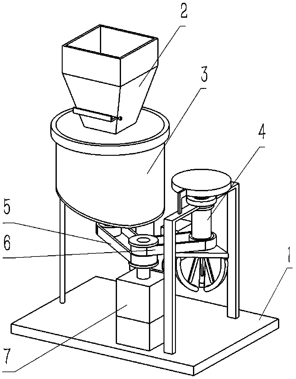
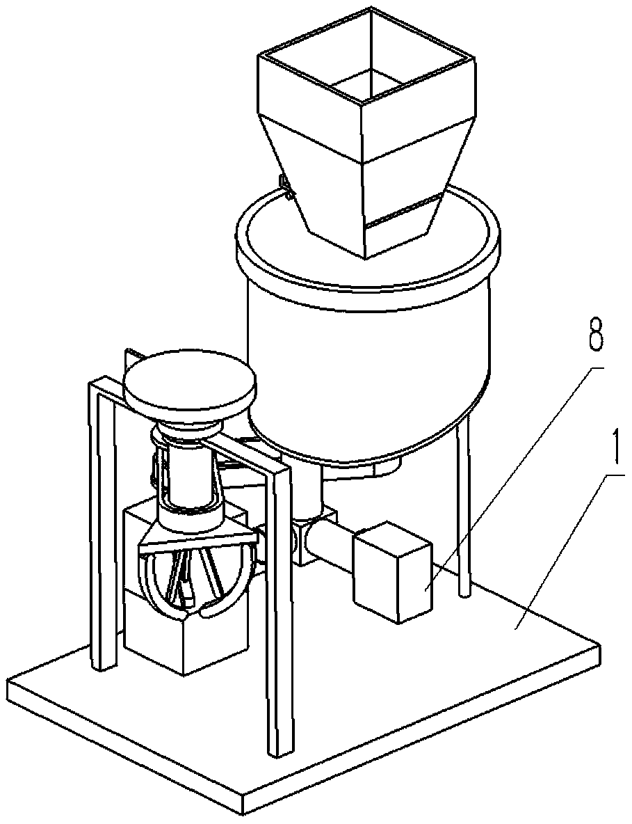
[0036] Combine below Figure 1-17 Describe this embodiment, a high-efficiency and energy-saving biomass gluing machine, including a chassis assembly 1, a feeding assembly 2, a melting furnace 3, a clamping assembly 4, a timing belt I5, a timing belt II6, and a power source 7 And the injection assembly 8, the feed assembly 2 is fixedly connected to the upper end of the melting material furnace 3 and the feeding assembly 2 communicates with the inner end of the melting material furnace 3, and the melting material furnace 3 is fixedly connected to the bottom frame assembly 1 The left end of the bottom frame assembly 4 is rotatably connected to the upper side of the right end of the bottom frame assembly 1, the power source 7 is fixedly connected to the front side of the bottom frame assembly 1, and the timing belt I5 is connected between the power source 7 and the melting furnace 3 , the synchronous belt II6 is connected between the power source 7 and the clamping assembly 4, the...
specific Embodiment approach 2
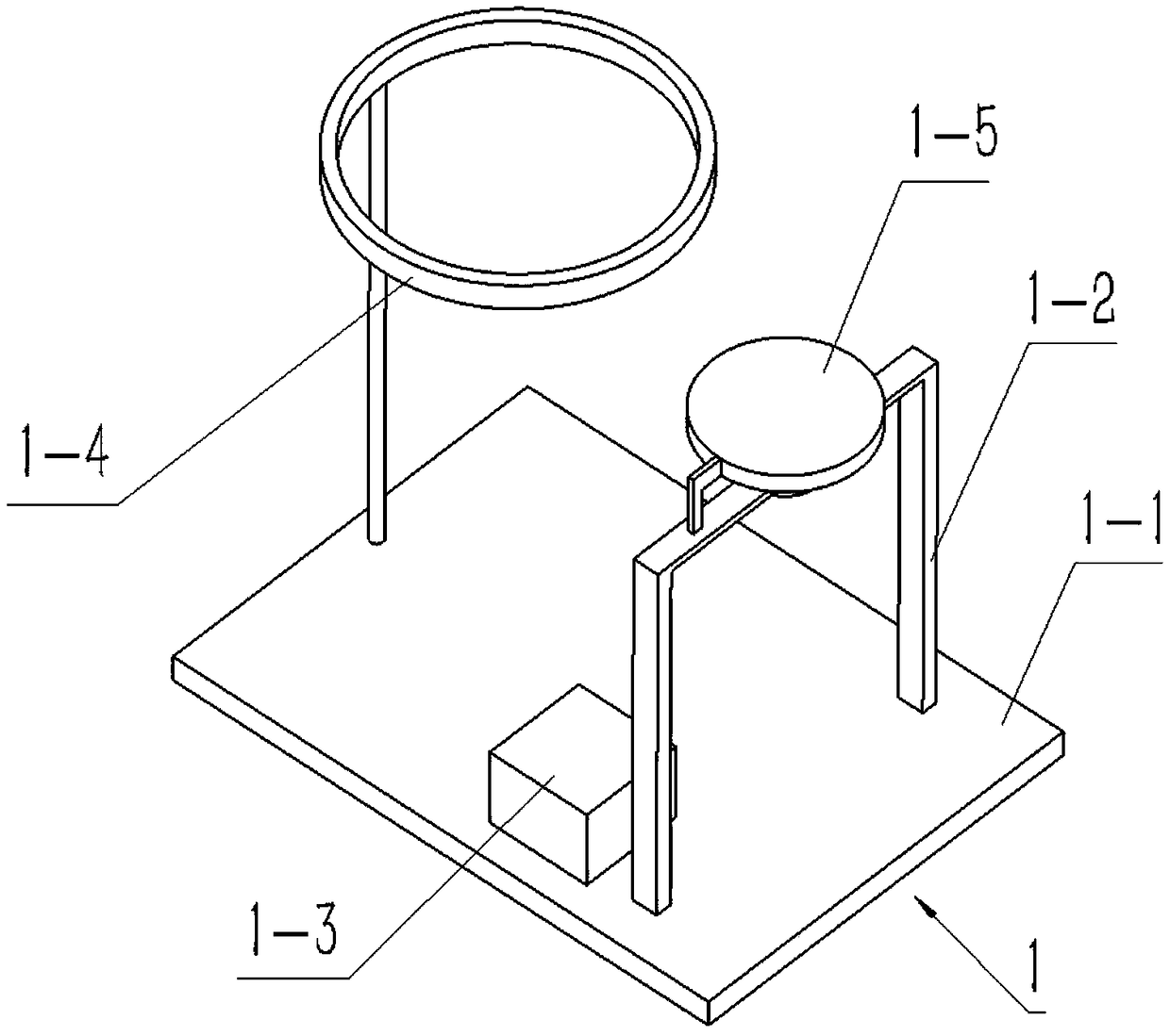
[0037] Combine below Figure 1-17 This embodiment will be described. This embodiment will further describe the first embodiment. The chassis assembly 1 includes a bottom plate 1-1, a right bracket 1-2, a fixing boss 1-3, a left fixing frame 1-4, Slot plate 1-5, slot plate fixing connecting rod 1-6, slot plate body 1-7, spiral groove 1-8 and flat groove 1-9, motor 1-10 and stepped pulley 1-11, right side bracket 1- 2 is fixedly connected to the right side of the upper end surface of the bottom plate 1-1-, the left fixed frame 1-4 is fixedly connected to the left side of the upper end surface of the bottom plate 1-1, and the fixed boss 1-3 is fixedly connected to the bottom plate 1- 1, the fixed boss 1-3 is located between the right side bracket 1-2 and the left side fixed frame 1-4, the slot plate 1-5 includes the slot plate fixing link 1-6, the slot plate body 1-7, The spiral groove 1-8 and the flat groove 1-9, the groove plate fixing connecting rod 1-6 are fixedly connected ...
specific Embodiment approach 3
[0039] Combine below Figure 1-17 Describe this embodiment, this embodiment will further explain the first embodiment, the feeding assembly 2 includes a feeding shell 2-1, a limit screw 2-2, a side slide plate 2-3, a chute 2-4, a screw thread Hole 2-5, two rectangular chute 2-6 and two rectangular slide blocks 2-7, the inner end of feeding shell 2-1 is hollowed out, and chute 2-4 is arranged on the feeding shell 2-1, slides The groove 2-4 runs through the feeding shell 2-1 left and right, the threaded hole 2-5 is set on the left side of the front face of the feeding shell 2-1, and the two rectangular chute 2-6 are respectively set at the front and back of the chute 2-4 On both sides, the threaded hole 2-5 communicates with the rectangular chute 2-6 on the front side of the chute 2-4, the limit screw 2-2 is threaded in the threaded hole 2-5, and the two rectangular sliders 2-7 are respectively Fixedly connected to the front and rear sides of the right end of the side slide pla...
PUM
 Abstract
Description
Claims
Application Information