Furniture 3D printer used for additive and subtractive hybrid machining

A 3D printer and compound processing technology, applied in the direction of additive processing, manufacturing auxiliary devices, etc., can solve the problems of long production cycle, large wood consumption, affecting product effect, etc., and achieve the effect of improving product effect

Active Publication Date: 2019-01-11
湖南哈工三维科技有限公司
View PDF6 Cites 1 Cited by
  • Summary
  • Abstract
  • Description
  • Claims
  • Application Information

AI Technical Summary

Problems solved by technology

Traditional furniture manufacturing is mostly connected through assembly, the appearance is limited and unsightly, some furniture has a long production cycle, numerous processes, and large wood consumption. While consuming a lot of manpower and material resources, it does not conform to our value direction of green environmental protection
[0003] The gap between the existing furniture 3D printer hopper and the material extrusion head is often easily blocked, resulting in uneven feeding of the material extrusion head and affecting the printing quality
Moreover, the surface of the current furniture 3D printer is often uneven after printing, which affects the product effect

Method used


Image

  • Furniture 3D printer used for additive and subtractive hybrid machining
  • Furniture 3D printer used for additive and subtractive hybrid machining
  • Furniture 3D printer used for additive and subtractive hybrid machining

Examples


Embodiment Construction

[0027] The following will clearly and completely describe the technical solutions in the embodiments of the present invention with reference to the accompanying drawings in the embodiments of the present invention. Obviously, the described embodiments are only some of the embodiments of the present invention, not all of them.

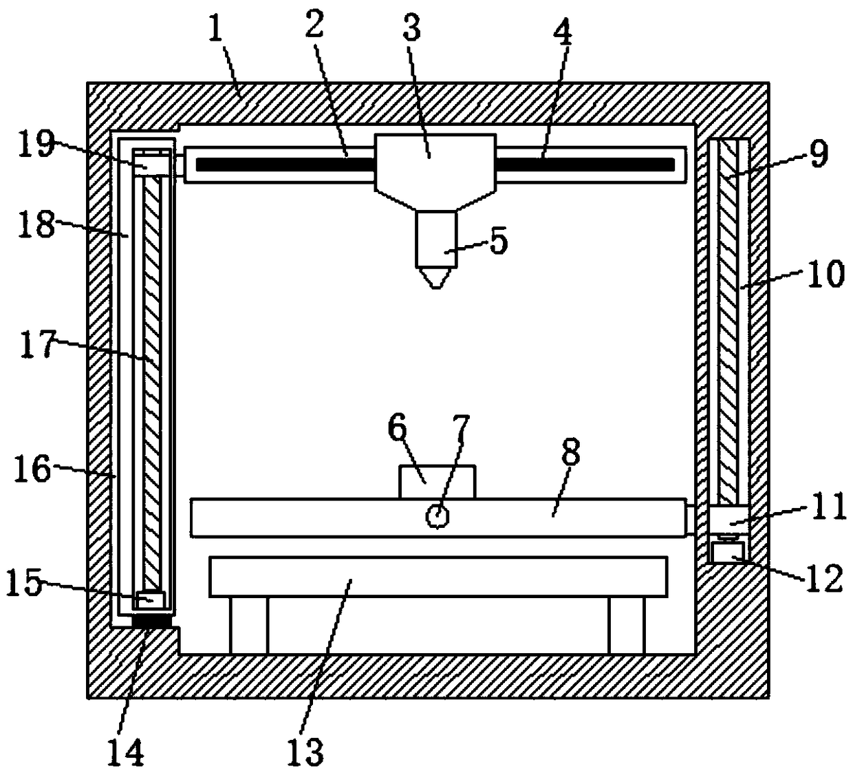
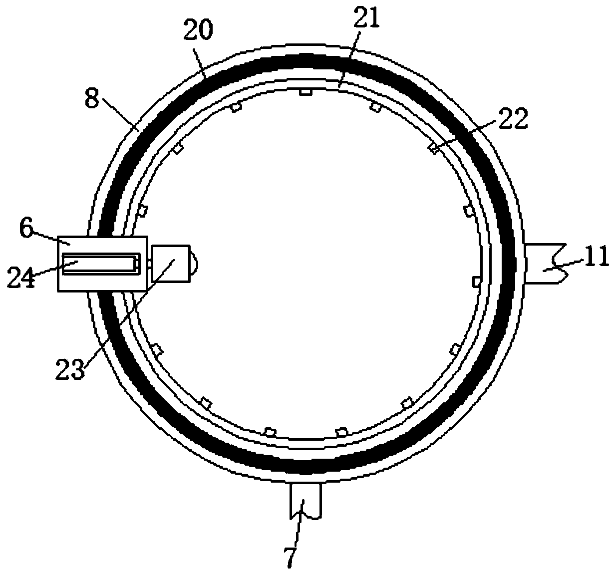
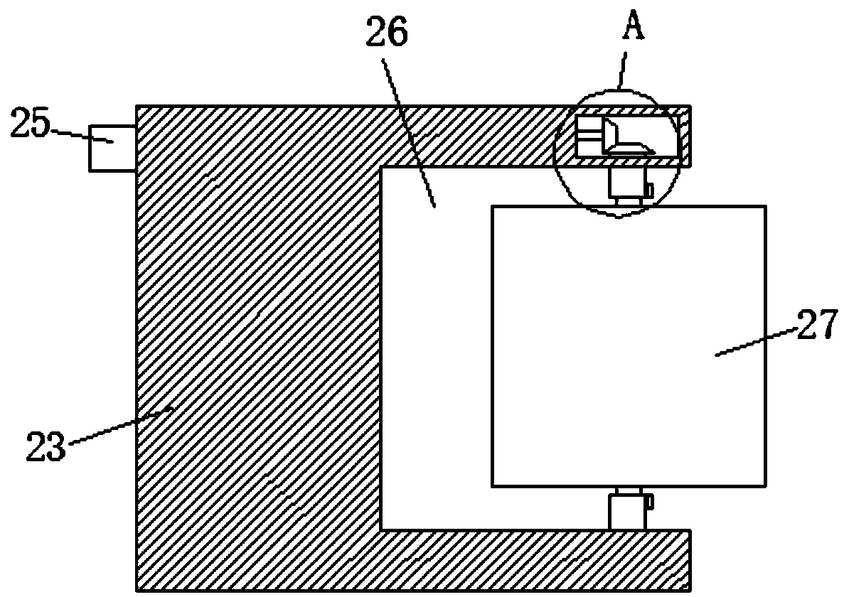
[0028] refer to Figure 1-6 , a furniture 3D printer for compound processing of adding and subtracting materials, comprising a housing 1, the inner bottom of the housing 1 is fixedly connected with a printing table 13, the left inner wall of the housing 1 is provided with a chute 16, and the inner wall of the lower end of the chute 16 is The first electric slide rail 14 arranged horizontally is fixedly connected, and the upper end of the first electric slide rail 14 is slidably connected with a slide bar 18. The slide bar 18 is provided with a first bar-shaped cavity, and the first bar-shaped cavity is provided with a height adjustment Mechanism, the he...


PUM


Abstract

The invention discloses a furniture 3D printer used for additive and subtractive hybrid machining. The furniture 3D printer used for additive and subtractive hybrid machining comprises a shell. A printing table is fixedly connected to the inner bottom of the shell. A sliding groove is formed in the inner wall of the left side of the shell. A first electric sliding rail which is horizontally arranged is fixedly connected to the inner wall of the lower end of the sliding groove. A sliding rod is slidably connected to the upper end of the first electric sliding rail. A first strip-shaped cavity is formed in the sliding rod. A height adjustment mechanism is arranged in the first strip-shaped cavity and is connected with a cross rod. A second electric sliding rail is fixedly connected to the side wall of the cross rod. A hopper is slidably connected to the side wall of the second electric sliding rail. A material extruding head is connected to the lower end of the hopper. A discharging portis formed in the lower end of the hopper. An abutting rod penetrates through the upper end of the hopper. The furniture 3D printer used for additive and subtractive hybrid machining is reasonable instructure; the discharging port can be dredged repeatedly, so that non-uniform feeding is avoided; and products can be rapidly cooled and can be polished, so that the product effect is better.

Description

technical field [0001] The invention relates to the technical field of furniture 3D printers, in particular to a furniture 3D printer for compound processing of adding and subtracting materials. Background technique [0002] 3D printers can not only "print" a complete building, but can even print the shapes of any objects needed by astronauts in spaceships. With the rapid development of science and technology, the demand for all kinds of beautiful and practical furniture has increased dramatically . Traditional furniture manufacturing is mostly connected through assembly, with limited and unattractive appearance. Some furniture has a long production cycle, numerous processes, and large wood consumption. While consuming a lot of manpower and material resources, it does not conform to our green value direction. [0003] The gap between the existing furniture 3D printer hopper and the material extrusion head is often easily blocked, resulting in uneven feeding of the material ...

Claims


Application Information

Patent Timeline
Patent Type & Authority Applications(China)
IPC IPC(8): B29C64/20B29C64/30
CPCB29C64/20B29C64/30
Inventor 薄冬生邓霞杨玲玉
Owner 湖南哈工三维科技有限公司
Why Eureka
Try Eureka