Eureka AIR delivers breakthrough ideas for toughest innovation challenges, trusted by R&D personnel around the world.

Wireless charging magnetic coupling structure and autonomous underwater vehicle system

An underwater vehicle, wireless charging technology, applied in charging stations, current collectors, electric vehicle charging technology and other directions, can solve the problems of limited battery capacity, limited battery life, pressure on the launch magnetic core, etc., to solve the problem of poor battery life, Ensure normal operation and improve the effect of adaptability

Active Publication Date: 2019-01-11
HARBIN INST OF TECH AT WEIHAI +1
View PDF10 Cites 4 Cited by
  • Summary
  • Abstract
  • Description
  • Claims
  • Application Information

AI Technical Summary

Problems solved by technology

However, due to the limitation of AUV's own volume and load capacity, the battery capacity is limited, and the battery life problem has always limited the further development of AUV.
At present, some magnetic coupling devices for wireless charging of AUVs have been proposed. At the transmitting end, the transmitting coil is often wound on the transmitting magnetic core, causing the shape and number of turns of the transmitting coil to be limited by the transmitting magnetic core, resulting in the setting of the transmitting coil. Restricted; and when charging on the seabed, the transmitting core and the AUV are basically bonded. Affected by seawater pressure, the shell at the transmitting end is squeezed, which directly causes the transmitting core to be compressed or even deformed, resulting in the magnetic permeability of the transmitting core. Changes that affect the normal operation of the system

Method used


Image

  • Wireless charging magnetic coupling structure and autonomous underwater vehicle system
  • Wireless charging magnetic coupling structure and autonomous underwater vehicle system
  • Wireless charging magnetic coupling structure and autonomous underwater vehicle system

Examples


Embodiment Construction

[0031] The present invention is described below based on examples, but the present invention is not limited to these examples. In the following detailed description of the present invention, some specific details are described in detail, and in order to avoid obscuring the essence of the present invention, known methods, procedures, procedures, and components are not described in detail.

[0032] Additionally, those of ordinary skill in the art will appreciate that the drawings provided herein are for illustrative purposes and are not necessarily drawn to scale.

[0033] Unless the context clearly requires, throughout the specification and claims, "comprises", "comprises" and similar words should be interpreted in an inclusive sense rather than an exclusive or exhaustive meaning; that is, "including but not limited to" meaning.

[0034] In the description of the present invention, it should be understood that the terms "first", "second" and so on are used for descriptive purp...


PUM


Abstract

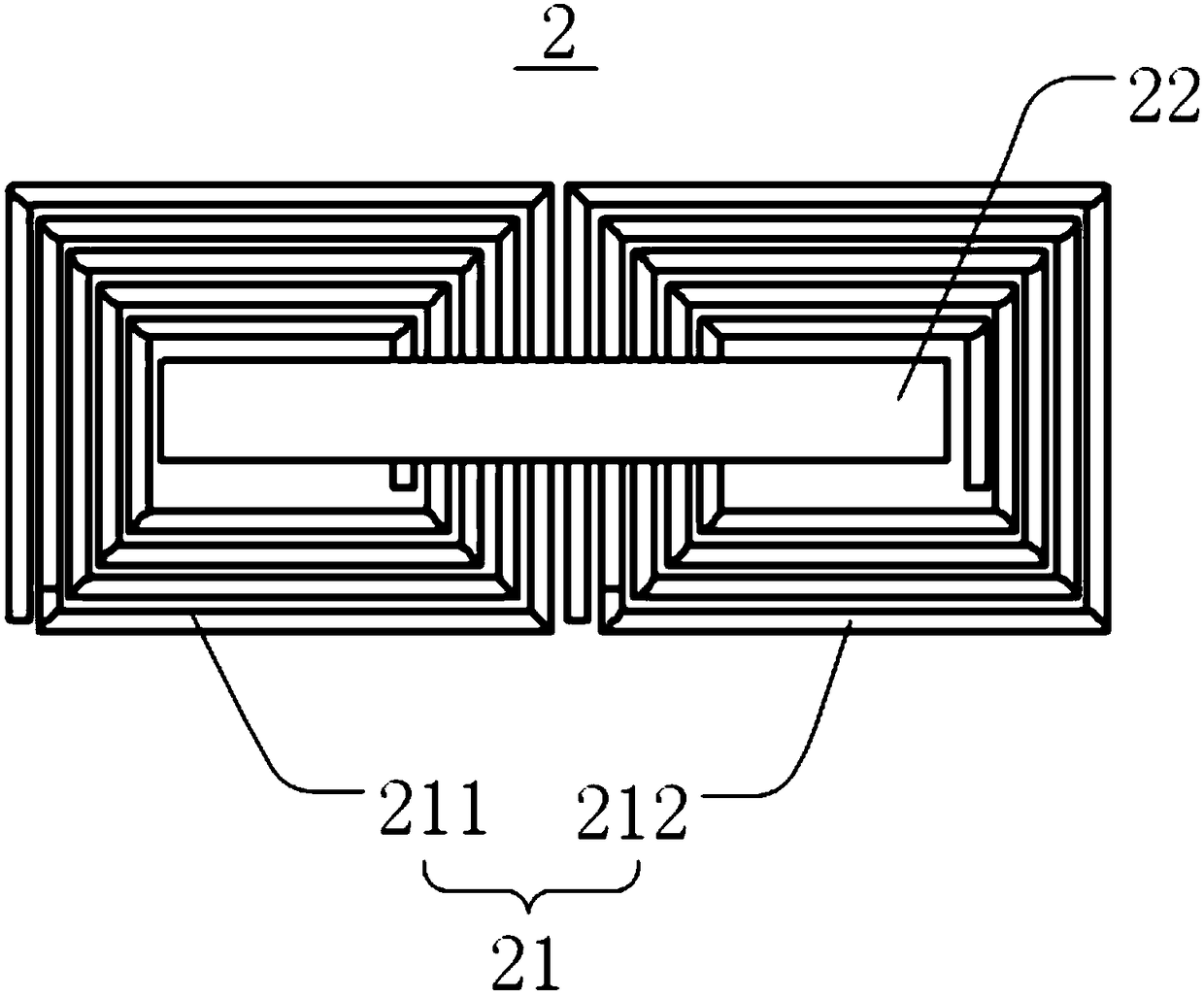
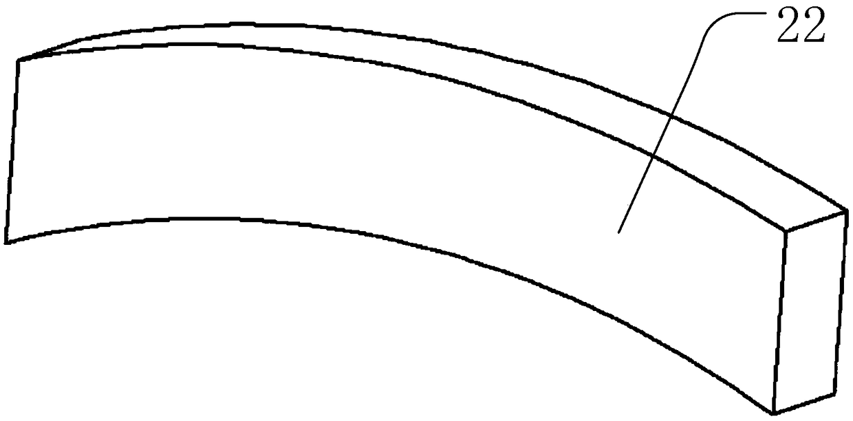
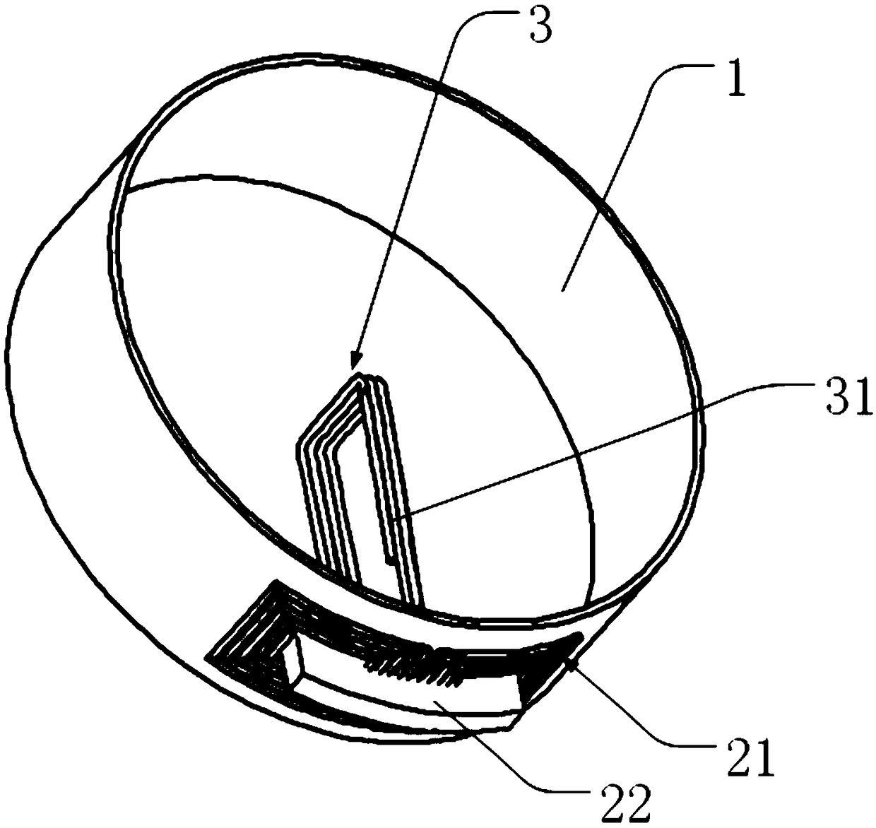
The invention discloses a wireless charging magnetic coupling structure and an autonomous underwater vehicle. The magnetic coupling structure is applied to an autonomous underwater vehicle and comprises a launching end arranged on a charging dock and a receiving end arranged on the autonomous underwater vehicle, wherein the launching end comprises a launching coil and a launching magnetic core arranged on a side of the launching coil remote from the autonomous underwater vehicle. The invention can help the autonomous underwater vehicle to realize the wireless charging of the seabed, and solvesthe problems of poor endurance and difficult charging of the autonomous underwater vehicle. The transmitting end of the magnetic coupling structure is provided with a transmitting magnetic core on one side of the transmitting coil, thereby reducing the limitation of the transmitting magnetic core on the transmitting coil and increasing the flexibility of the transmitting coil, and the distance between the magnetic core of the transmitting end, and the autonomous underwater vehicle is reserved to avoid the seawater pressure changing the parameters of the transmitting magnetic core, so as to improve the adaptability of the system to underwater wireless charging.

Description

technical field [0001] The invention relates to the technical field of wireless charging, in particular to a magnetic coupling structure of wireless charging and an autonomous underwater vehicle system. Background technique [0002] There are a lot of biological resources and mineral resources in the ocean, but human beings still know very little about the ocean. Autonomous underwater vehicle AUV (Autonomous underwater vehicle) is an important tool to help humans understand and explore the ocean. In recent years, although AUV has played an important role in marine national defense security, marine environmental observation, and marine resource exploration. However, due to the limitation of AUV's own size and load capacity, the battery capacity is limited, and the battery life problem has always limited the further development of AUV. There are two traditional methods for charging AUVs: the first is to salvage the AUV to the mother ship every time the battery is exhausted, ...

Claims


Application Information

Patent Timeline
Patent Type & Authority Applications(China)
IPC IPC(8): B60L53/12H02J7/00H02J50/10H02J5/00
CPCH02J5/005H02J7/025H02J50/10B60L2200/32Y02T10/70Y02T10/7072Y02T90/14
Inventor 蔡春伟武帅秦沐刘金泉张言语任秀云
Owner HARBIN INST OF TECH AT WEIHAI
Why Eureka
Eureka Blog
Learn More