[0028] In order to make the objectives, technical solutions and advantages of the present invention clearer, the embodiments of the present invention will be described in further detail below in conjunction with the accompanying drawings.
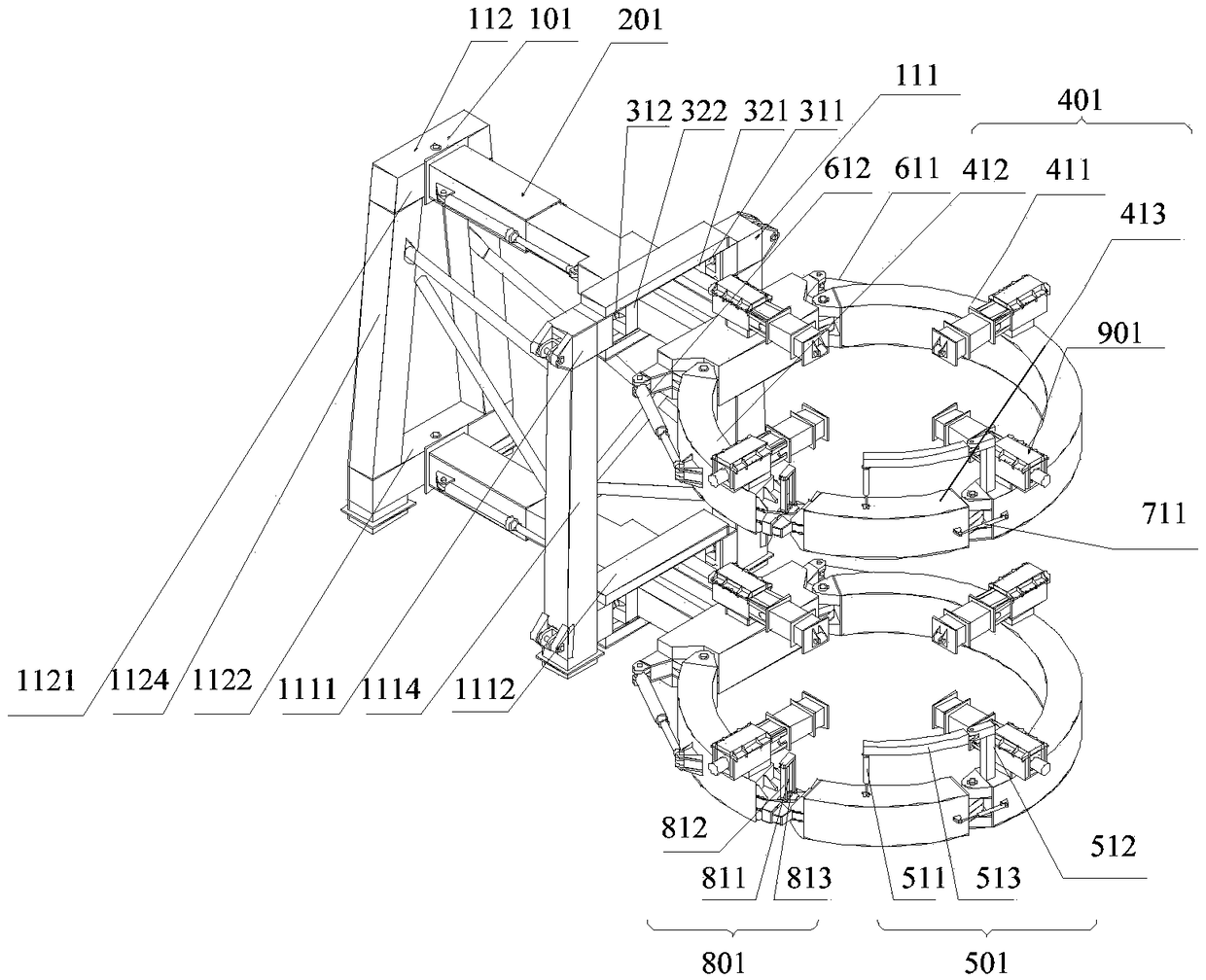
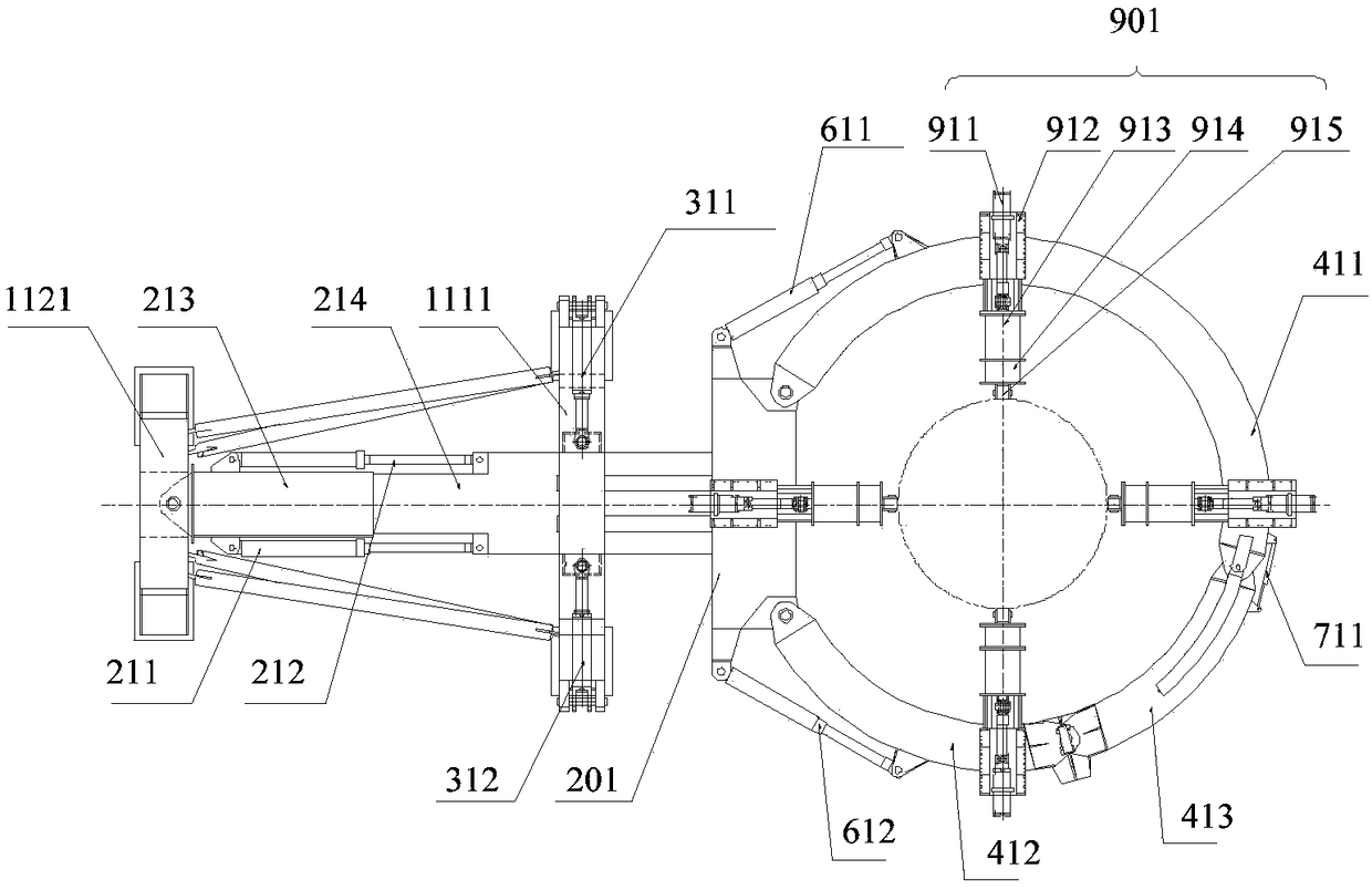
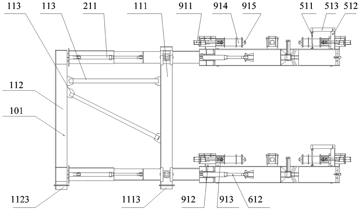
[0029] figure 1 It is a schematic structural diagram of a pile holder provided by an embodiment of the present invention. Such as figure 1 As shown, the pile holder includes a mounting base 101, a main pushing mechanism 201, and a clamping arm assembly 401. The mounting base 101 is fixedly connected to the deck of the ship, the main pushing mechanism 201 is mounted on the mounting base 101, and the main pushing mechanism 201 is a cantilever structure. The clamping arm assembly 401 includes a first clamping arm 411, a second clamping arm 412, and a third clamping arm 413. The protruding end of the main pushing mechanism 201 is hinged to the first end of the first clamping arm 411, and the protruding end of the main pushing mechanism 201 is hinged with The first end of the second clamp arm 412 is hinged. The second end of the first clamping arm 411 is hinged to the first end of the third clamping arm 413, the second end of the third clamping arm 413 and the second end of the second clamping arm 412 are detachably connected by a pin, the first clamping arm 411. The second clamping arm 412 and the third clamping arm 413 form an annular structure when they are closed, which is convenient for fixing the foundation pile.
[0030] In the embodiment of the present invention, the first clamping arm 411, the second clamping arm 412, and the third clamping arm 413 are all arc-shaped clamping arms. When the first clamping arm 411, the second clamping arm 412 and the third clamping arm 413 are closed Form a circular ring structure. In other embodiments, the first clamping arm 411, the second clamping arm 412, and the third clamping arm 413 may also be clamping arms of other shapes.
[0031] See figure 1 The clamping arm assembly 401 also includes a first pile-holding cylinder 611 and a second pile-holding cylinder 612. One end of the first pile-holding cylinder 611 is hinged with the extension end of the main thrust mechanism 201, and the other end of the first pile-holding cylinder 611 is hinged with the first clamping arm 411, so that when the first pile-holding cylinder 611 contracts or extends, The first clamping arm 411 can be opened outward or gathered inward. One end of the second pile-holding cylinder 612 is hinged with the extended end of the main thrust mechanism 201, and the other end of the second pile-holding cylinder 612 is hinged with the second clamping arm 412, so that when the second pile-holding cylinder 612 contracts or extends, The second clamping arm 412 may be opened outward or gathered inward.
[0032] Such as figure 1 As shown, the clamping arm assembly 401 also includes an opening and closing cylinder 711, one end of the opening and closing cylinder 711 is hinged to the second end of the first clamping arm 411, and the other end of the opening and closing cylinder 711 and the first end of the third clamping arm 413 are hinged. It is hinged so that when the opening and closing cylinder is contracted or extended, the third clamp arm can be opened outward or gathered inward.
[0033] Such as figure 1 As shown, the clamp arm assembly 401 further includes a cantilever cylinder assembly 501, and the cantilever cylinder assembly 501 includes a cantilever cylinder 511, a fixed arm 512 and a cantilever 513. One end of the cantilever cylinder 511 is vertically arranged on the upper surface of the third clamping arm 413, the fixed arm 512 is arranged on the upper surface of the second end of the first clamping arm 411, one end of the cantilever 513 is connected to the other end of the cantilever cylinder 511, and the other end of the cantilever 513 One end is connected to the fixed arm 512.
[0034] figure 2 It is a top view of a pile holder provided by an embodiment of the present invention. Such as figure 1 with figure 2 As shown, the clamping arm assembly 401 further includes a plurality of correction cylinder assemblies 901, and the plurality of correction cylinder assemblies 901 are evenly spaced on the annular structure formed by the first clamping arm 411, the second clamping arm 412, and the third clamping arm 413 , And the telescopic ends of the plurality of correction oil cylinder assemblies 901 all face the center of the ring structure.
[0035] The embodiment of the present invention realizes the opening and closing control of the first clamping arm 411, the second clamping arm 412, and the third clamping arm 413 by setting the first pile holding cylinder 611, the second pile holding cylinder 612, and the opening and closing cylinder 711 to facilitate Insert the single pipe pile. Specifically, when the first pile-holding cylinder 611, the second pile-holding cylinder 612, and the opening and closing cylinder 711 contract, the first clamping arm 411, the second clamping arm 412, and the third clamping arm 413 are opened, and the foundation piles can be placed smoothly . When the first pile-holding cylinder 611, the second pile-holding cylinder 612, and the opening and closing cylinder 711 are extended, the first clamping arm 411, the second clamping arm 412, and the third clamping arm 413 are closed. After the clamping arms are closed, through adjustment The elongation length of the correcting cylinder assembly 901 is adjusted in time to adjust the verticality of the foundation piles to achieve fixed support for the foundation piles. At the same time, when the first clamping arm 411, the second clamping arm 412, and the third clamping arm 413 are closed, there is a certain height difference between the second end of the second clamping arm 412 and the second end of the third clamping arm 413. At this time, The height adjustment of the second end of the third clamping arm 413 is realized by the cantilever cylinder 511, so that the second end of the second clamping arm 412 and the second end of the third clamping arm 413 are kept on the same plane, which is convenient for the connection of the two and simple operation ,save time and energy.
[0036] Such as figure 1 As shown, the pile holder may further include a bolt cylinder assembly 801, which includes a bolt cylinder 811, a cylinder bracket 812, and a bolt 813. The cylinder bracket 812 is arranged on the upper surface of the second end of the second clamping arm 412, the pin cylinder 811 is fixed on the cylinder bracket 812, one end of the pin cylinder 811 is connected to the cylinder bracket 812, and the other end of the pin cylinder 811 is connected to the pin 813. When the first clamping arm 411, the second clamping arm 412, and the third clamping arm 413 are closed, the pin cylinder 811 controls the pin 813 to be inserted into the socket on the second end of the third clamping arm 413 to realize the second clamping arm 412. The two ends and the second end of the third clamp arm 413 are detachably connected.
[0037] image 3 It is a front view of a pile holder provided by an embodiment of the present invention. Such as image 3 As shown, the mounting seat 101 includes a front leg 111, a rear leg 112, and a connecting rod 113. The front leg 111 and the rear leg 112 are vertically spaced apart, and the front leg 111 and the rear leg 112 pass through the connecting rod 113. For connection, a front support 1113 is provided at the bottom of the front leg 111, a rear support 1123 is provided at the bottom of the rear leg 112, and the front support 1113 and the rear support 1123 are bolted to the support on the hull deck.
[0038] Preferably, a plurality of front supports 1113 are symmetrically provided at the bottom of the front leg 111, and a plurality of rear supports 1123 are symmetrically provided at the bottom of the rear leg 112 to achieve a stable connection with the hull deck support.
[0039] Such as figure 1 As shown, the front leg 111 may include a front leg upper beam 1111, a front leg lower beam 1112, and two front leg support columns 1114. The front leg upper beam 1111 and the front leg lower beam 1112 are arranged in parallel, and the front support Both ends of the upper leg cross beam 1111 are fixedly connected to one end of the two front leg support columns 1114, and the two ends of the front leg lower cross beam 1112 are respectively fixedly connected to the other end of the two front leg support columns 1114. The rear leg 112 may include a rear leg upper beam 1121, a rear leg lower beam 1122, and two rear leg support columns 1124, and the structure of the rear leg is the same as that of the front leg. Such as figure 1 As shown, the pile holder includes two main pushing mechanisms 201 and two clamping arm assemblies 401. One of the two main pushing mechanisms 201 is provided on the front leg upper cross beam 1111 and the rear leg upper beam 1121, and the other of the two main pushing mechanisms 201 is provided on the front leg lower cross beam 1112 and the rear leg. On the lower beam 1122 of the leg.
[0040] Specifically, one end of the main pushing mechanism 201 is hinged to the upper cross beam 1121 of the rear leg, and the other end passes through the upper cross beam 1111 of the front leg. One end of the other main pushing mechanism 201 is hinged on the lower cross beam 1122 of the rear leg, and the other end passes through the lower cross beam 1112 of the front leg.
[0041] Such as figure 2 As shown, the main pushing mechanism 201 includes a first main pushing cylinder 211, a second main pushing cylinder 212, a rotating arm 213, and a telescopic arm 214. One end of the rotating arm 213 is hinged on the upper cross beam 1121 of the rear leg or the lower cross beam 1122 of the rear leg. One end of the telescopic arm 214 is telescopically sleeved in the other end of the rotating arm 213, and the other end of the telescopic arm 214 passes through the front support. The upper leg beam 1111 or the front leg lower beam 1112, the first main thrust cylinder 211 and the second main thrust cylinder 212 are symmetrically distributed on both sides of the main thrust mechanism 201, one end of the first main thrust cylinder 211 is hinged with the rotating arm 213, the first main thrust cylinder The other end of the 211 is hinged with the telescopic arm 214, one end of the second main thrust cylinder 212 is hinged with the rotating arm 213, and the other end of the second main thrust cylinder 212 is hinged with the telescopic arm 214. The first main thrust cylinder 211 and the second main thrust cylinder 212 work synchronously. When the first main thrust cylinder 211 and the second main thrust cylinder 212 extend at the same time, the telescopic arm is driven to extend. When the first main thrust cylinder 211 and the second main thrust cylinder 212 simultaneously extend When retracting, the telescopic arm is driven to retract. By controlling the first main thrust cylinder 211 and the second main thrust cylinder 212, the length of the telescopic boom can be adjusted, which can make the ring center of the pile holder coincide with the center of the foundation pile, and improve the accuracy of piling operations.
[0042] Specifically, such as figure 1 As shown, a through hole is provided in the middle of the upper cross beam 1111 of the front leg and the lower cross beam 1112 of the front leg. The telescopic arm 214 passes through the through hole on the upper cross beam 1111 of the front leg or the lower cross beam 1112 of the front leg.
[0043] Figure 4 It is a schematic diagram of the lateral movement of a pile holder provided by an embodiment of the present invention. Such as Figure 4 As shown, the pile holder also includes a first side pushing cylinder 311 and a second side pushing cylinder 312. The first side pushing cylinder 311 and the second side pushing cylinder 312 are respectively arranged on both sides of the middle through hole of the upper cross beam 1111 of the front leg. And it is arranged perpendicular to the telescopic arm 214. One end of the first side thrust cylinder 311 is hinged with the end of the upper cross beam 1111 of the front leg. The other end of the first side thrust cylinder 311 is hinged with a first side thrust sliding block 321. The pushing sliding block can slide along the upper cross beam 1111 of the front leg with the expansion and contraction of the first side pushing cylinder 311. The structure of the second side push cylinder 312 is the same as the structure of the first side push cylinder 311. The first side push slider 321 and the second side push block 322 are sandwiched on opposite sides of the telescopic arm 214.
[0044] When one side push cylinder extends and the other side push cylinder retracts, the side push slider can push the telescopic arm to slide in the through hole of the front leg beam along the direction of the beam, thereby driving the rotating arm to rotate and realizing the entire main thrust mechanism Rotation makes it convenient for the ring center of the pile holder to coincide with the center of the pile foundation of the single pipe pile, thereby improving the accuracy of piling operations.
[0045] Preferably, on the side of the front leg upper cross beam 1111 or the front leg lower cross beam 1112 that is in contact with the telescopic arm 214, a slideway (not shown in the figure) along the direction of the front leg upper beam is provided. The slideway can reduce friction during the sliding process of the telescopic arm 214 and improve the sensitivity of the telescopic arm sliding.
[0046] Furthermore, two rows of slideways are arranged on each beam to further reduce friction.
[0047] Figure 5 It is a schematic diagram of an open state of a pile holder provided by an embodiment of the present invention. Such as Figure 5 As shown, the end surface A of the second end of the second clamping arm 412 is a vertical vertical surface, and the end surface B of the second end of the third clamping arm 413 is a vertical vertical surface. When the first clamping arm 411, the second clamping arm 412, and the third clamping arm When 413 is closed, the vertical end surface of the second clamp arm 412 away from the main pushing mechanism 201 and the vertical end surface of the third clamp arm 413 away from the first clamp arm 411 form a surface contact. Under the action of the latch, the second clamp is restrained All the degrees of freedom of the arm 412 and the third clamping arm 413 transform the unstable structure of the entire clamping arm assembly structure from the 4 twisting points into a stable structure with 3 twisting points, increasing the stability of the clamping arm assembly and improving the fixation of the single pipe pile The ability to support.
[0048] Further, as figure 2 As shown, each correction cylinder assembly 901 includes a correction cylinder 911, a correction seat 912, a correction arm 913 and a roller assembly 915. The correction seat 912 can be arranged on the horizontal end surfaces of the first clamping arm 411, the second clamping arm 412 and the third clamping arm 413. One side of the correction cylinder 911 is connected with the vertical flange of the correction base 912, and the other side of the correction cylinder 911 It is hinged with the deviation correction arm 913, and a roller assembly 915 is installed at the front end of the deviation correction arm 913.
[0049] Preferably, such as Figure 5 As shown, the roller assembly 915 includes a roller 9151 and a roller fixing seat 9152, and the roller 9151 and the roller fixing seat 9152 are arranged tangentially.
[0050] Specifically, the clamp arm assembly 401 may include 4 correction cylinder assemblies 901, which are evenly distributed in the circumferential direction of the ring structure, so that the verticality of the foundation pile can be adjusted accurately, and the verticality of the foundation pile can meet the design requirements. standard requirement.
[0051] Further, according to the actual construction pile diameter, a tooling arm 914 can be installed between the correction arm 913 and the roller assembly 915 to meet the fixed support requirements of different single-pipe pile diameters.
[0052] Preferably, an upper cover plate (not marked in the figure) is provided on the correction seat 912 to prevent the correction cylinder from affecting the service life in the harsh ocean environment. The upper cover plate can be a bolt connection structure and connected to the correction seat 912 for easy disassembly .
[0053] Further, as figure 1 As shown, the hinge point of the fixed arm 512 and the cantilever 513 of the cantilever cylinder assembly 501 and the hinge point of the second clamp arm 412 and the third clamp arm 413 are arranged concentrically, so that the cantilever 513 and the third clamp arm 413 rotate along the hinge point. Synchronization improves the stability of the cantilever cylinder assembly 501.
[0054] Image 6 It is a hydraulic schematic diagram of a pile holding cylinder of a pile holding device provided by an embodiment of the present invention. Further, the rod-mounted cavity 6111 and the rod-less cavity 6112 of the first pile-holding cylinder 611 are connected through a solenoid valve, and the hydraulic control oil circuit of the first pile-holding cylinder 611 may be as follows Image 6 Shown. Both the rod cavity and the rodless cavity of the first pile-holding cylinder 611 and the second pile-holding cylinder 612 can be connected through two solenoid valves DT1 and DT2. During the piling operation, control the solenoid valve of the first pile-holding cylinder 611 and the second pile-holding cylinder 612 to conduct, and the rod cavity is connected with the rodless cylinder, so that the piston rod is in a floating state, and the force and impact generated during the piling process are avoided Therefore, the specifications of the cylinder can be reduced and the life of the cylinder can be extended.
[0055] Such as Image 6 As shown, the control oil circuit of the pile holding cylinder further includes a one-way valve 1, a one-way valve 2, a one-way valve 3, an overflow valve 4, and an overflow valve 5. The oil inlet of the one-way valve 1 communicates with the pipeline oil inlet A and the pipeline oil inlet B, and the oil outlet of the one-way valve 1 communicates with the rodless cavity of the pile holding cylinder. The oil inlet of the one-way valve 2 is communicated with the pipeline oil inlet A and the pipeline oil inlet B, and the oil outlet of the one-way valve 2 communicates with the pile holding cylinder with a rod cavity. The rodless cavity of the pile-holding cylinder is connected with the first oil port of the overflow valve 4, the second oil port of the overflow valve 4 is connected with the oil inlet of the check valve 3, and the oil outlet of the check valve 3 is connected with the oil return pipeline T is connected. The pile-holding cylinder has a rod cavity connected with the first oil port of the overflow valve 5, and the second oil port of the overflow valve 5 is connected with the oil return pipeline T. When the pile-holding cylinder is extended, the hydraulic oil flows into the rodless cavity of the pile-holding cylinder through the pipeline inlet A and the pipeline inlet B through the check valve 1, and the excess hydraulic oil in the rod cavity passes through the overflow valve 5 Flow back to the oil return line T. When the pile holding cylinder is shortened, the hydraulic oil flows into the rod cavity of the pile holding cylinder through the pipeline inlet A and pipeline inlet B through the check valve 2, and the excess hydraulic oil in the rodless cavity passes through the overflow valve 6 The check valve 3 flows back to the oil return line T.
[0056] At the same time, the rodless cavity of the pile holding cylinder is connected with the solenoid valve DT1, and the pile holding cylinder has a rod cavity connected with the solenoid valve DT2. When the solenoid valve DT1 and DT2 are in the normal state, the solenoid valve DT1 is in the upper position, the check valve 7 closes the oil circuit, the solenoid valve DT2 is in the lower position, the check valve 6 closes the oil circuit, and the rod cavity and the rodless cavity are not connected . When the solenoid valve DT1 and the solenoid valve DT2 are energized, the solenoid valve DT1 is in the lower position, and the solenoid valve DT2 is in the upper position, the oil circuit is open, the overflow valve 4, the overflow valve 5, the one-way valve 1 and the one-way valve 2 Close to realize the connection between the rod cavity of the pile holding cylinder and the rodless cavity of the pile holding cylinder.
[0057] The use process of the pile holder in the embodiment of the present invention can be divided into the following steps:
[0058] A. In the towing state, the main thrust cylinder is fully retracted, the side thrust cylinder is in the neutral position to lock the main thrust arm, the pile holding cylinder is fully extended, the correction cylinder is fully retracted, the opening and closing cylinder is fully extended, and the latch cylinder is fully extended. In the fully extended state, the latch is inserted to lock the first clamp arm, the second clamp arm and the third clamp arm.
[0059] B. When towing to the piling position, extend the 4 main thrust cylinders on the upper and lower floors at the same time, retract the latch cylinder, open and close the cylinder, and the pile holding cylinder in turn, and open the first clamp arm, second clamp arm and third clamp arm.
[0060] C. Lift the pile foundation into the center of the pile holder, and then extend the pile holding cylinder, open and close the cylinder in turn, observe the height difference between the pile holding closing arm and the pile holding small clamping arm, retract the cantilever cylinder to make the third clamping arm and The second clamping arm is at the same height, and the opening and closing cylinder is used to make the end surface of the third clamping arm B and the end surface of the second clamping arm A fit, extend the pin cylinder, close the pile holder into a ring, and lock it with a pin.
[0061] D. After inserting the plug, the pile holding cylinders DT1 and DT2 are energized, see Image 6 , Make the pile holding cylinder have rod cavity and rodless cavity to communicate, the pile holding cylinder piston rod is in a floating state, release the pile holding cylinder, so that the pile holding cylinder is not stressed during the pile driving process.
[0062] E. Simultaneously extend 8 correction cylinders on the upper and lower layers, and adjust the verticality of the foundation piles in time by adjusting the elongation length of the correction cylinders to realize the fixed support of the foundation piles.
[0063] F. According to the actual position of the pile foundation, it is necessary to move the telescopic main push cylinder back and forth or the telescopic side push cylinder to move left and right to adjust the pile foundation to the piling position to start the piling operation.
[0064] The above descriptions are only preferred embodiments of the present invention and are not intended to limit the present invention. Any modification, equivalent replacement, improvement, etc. made within the spirit and principle of the present invention shall be included in the protection of the present invention. Within range.