Excavator movable arm hydraulic control system and lifting control method

A technology of hydraulic control system and mobile arm, which is applied to mechanically driven excavators/dredgers, earth movers/shovels, construction, etc., and can solve the problem of reduced digging force of the stick, slow digging efficiency, and lower stroke of the boom Long-term problems, to achieve the effect of reducing fuel consumption and improving operating efficiency

Active Publication Date: 2019-01-11
LIUZHOU LIUGONG EXCAVATORS +2
View PDF4 Cites 14 Cited by
  • Summary
  • Abstract
  • Description
  • Claims
  • Application Information

AI Technical Summary

Problems solved by technology

The pressure in both the large chamber and the small chamber of the boom cylinder increases, resulting in an increase in system load, unreasonable use of energy, and high fuel consumption
[0007] 2. During the operation of the breaker, in order to prevent the drill rod from producing idle stroke operation, it is necessary to output hydraulic oil to the small cavity of the boom cylinder, use the working device to prop up the front end of the excavator, and tilt the machine about 10° to make the breaker The drill rod of the hammer is always pressed against the broken rock, but the tilt of the whole machine makes the driver's sitting position uncomfortable
[0008] 3. When digging deep trenches, the bucket is at a lower position, and the digging force of the stick is reduced. It needs to be lifted with the boom to dig, and the digging efficiency is slow.
At the same time, the lower stroke of the boom is long during deep trench excavation, which consumes a lot of energy

Method used


Image

  • Excavator movable arm hydraulic control system and lifting control method
  • Excavator movable arm hydraulic control system and lifting control method

Examples


Embodiment Construction

[0028] The specific implementation will be described below in conjunction with the accompanying drawings.

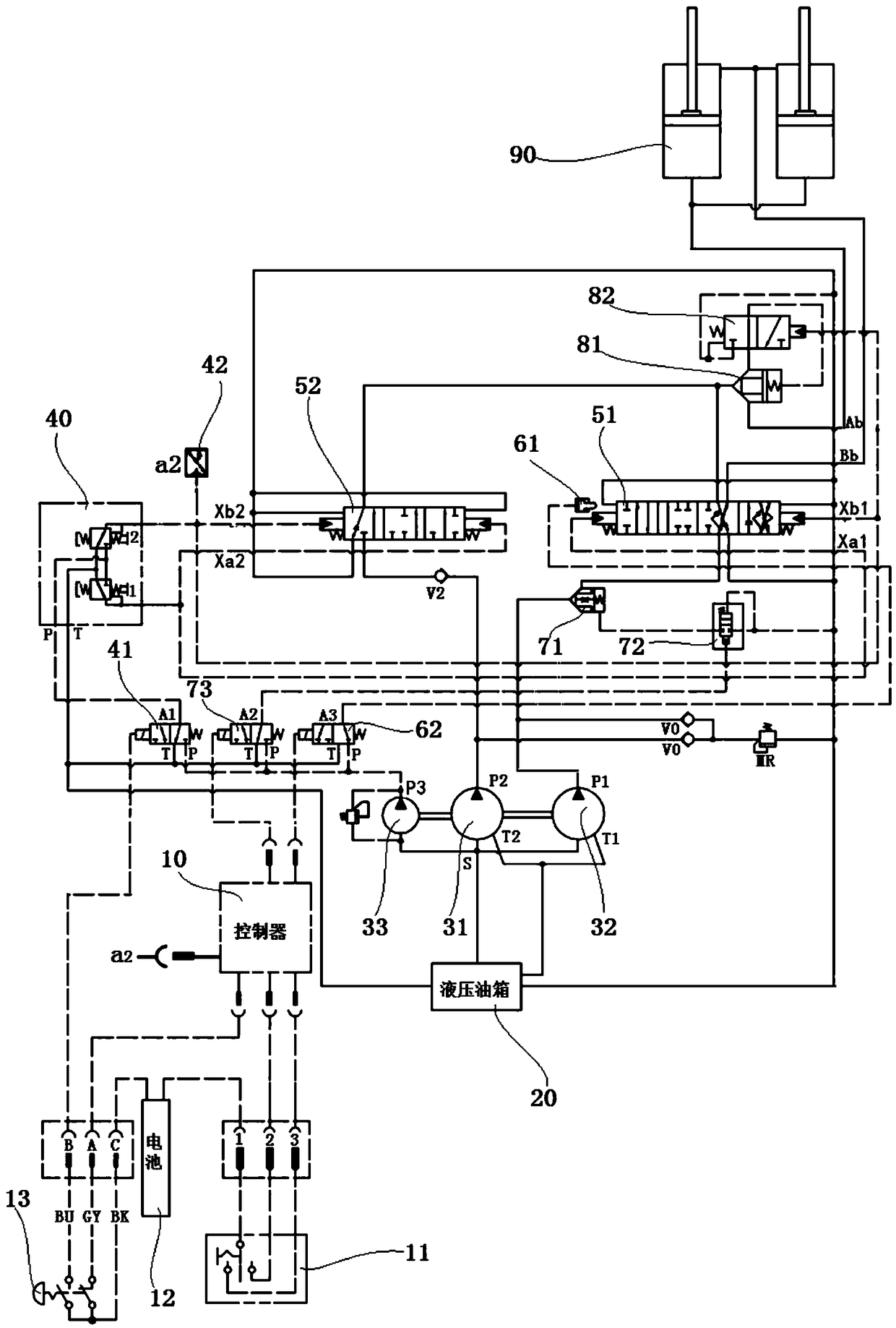
[0029] Such as figure 1 As shown, the excavator arm hydraulic control system in this embodiment includes a lift confluence valve 52 and a control main valve 51 for controlling the boom cylinder 90, and a liquid control terminal connected with the lift confluence valve 52 and the control main valve 51 The connected pilot control device, the hydraulic oil tank 20 connected to the oil tank circuit, the left pump 31 , the right pump 32 and the pilot pump 33 connected to the oil inlet S and the hydraulic oil tank 20 .

[0030] The pump port P2 of the left pump 31 is connected to the working oil inlet port of the lift confluence valve 52 through the one-way valve V2, and the connection port of the large cavity of the boom cylinder of the lift confluence valve 52 is connected to the large cavity of the boom cylinder of the control main valve 51 The ports are connected to the l...


PUM


Abstract

The invention relates to an excavator movable arm hydraulic control system for reducing the oil consumption in operation of an excavator and preferably meeting the working demands under common workingconditions. In the excavator movable arm hydraulic control system, a fourth station of a control main valve is used as a movable arm two-way floating work station; a movable arm downward floating oilway is arranged in an oil way in a third work station; a fourth work station for limiting the moving travel of a valve element is provided for enabling a control device; a right oil port of a right pump is connected with an oil inlet of a control main valve through an oil inlet stop valve; the oil inlet stop valve is stopped only when a movable arm is descended and a one-way or two-way floating mode is performed; otherwise, the oil inlet stop valve is located in a conducted state; the control device is enabled by the fourth work station; the enabled state is located only when the movable armis descend and the two-way floating mode is performed; otherwise, a prohibited state is located; and through an electromagnetic valve, the oil inlet stop valve and the fourth work station are controlled to enable the control device. Through switching of working modes, different working demands are met, so that the oil consumption can be reduced, and the operation efficiency is improved.

Description

technical field [0001] The present invention relates to an excavator hydraulic system, more specifically, relates to an excavator arm hydraulic control system and a lifting control method. Background technique [0002] Most of the boom control of existing excavators adopts dual-pump oil supply, in which the boom lifting control is controlled by the control main valve and the lift confluence valve, and the liquid control ends of the control main valve and the lift confluence valve are connected to The pilot oil circuit is connected, the oil inlet of the lift confluence valve is connected with the left pump, the oil inlet of the control main valve is connected with the right pump, the large chamber of the boom cylinder of the lift confluence valve is connected with the oil port of the boom control valve The large cavity of the oil cylinder is connected to the oil port and connected to the oil circuit through the large cavity of the boom cylinder. The control valve and the pipe...

Claims


Application Information

Patent Timeline
Patent Type & Authority Applications(China)
IPC IPC(8): E02F3/43E02F9/22
CPCE02F3/43E02F9/22E02F9/2264E02F9/2292
Inventor 韦磊石子贡李香龙卢春霖秦付华宾旭洲程昭荣
Owner LIUZHOU LIUGONG EXCAVATORS
Why Eureka
Try Eureka