
An axial anti-shock device

An anti-shock, axial technology, used in jet propulsion devices, gas turbine devices, machines/engines, etc., can solve problems such as excessive local stress, poor ability to withstand axial force, and easy deformation, and achieve a simple and balanced structure. Axial force and thermal stress, the effect of solving stress concentration

Active Publication Date: 2019-09-06
AECC SHENYANG ENGINE RES INST
View PDF3 Cites 0 Cited by
  • Summary
  • Abstract
  • Description
  • Claims
  • Application Information

AI Technical Summary

Problems solved by technology

The disadvantage is: in the case of axial impact, only the main support can bear the force, and the auxiliary support cannot bear the force, so the stress is relatively concentrated, which is easy to cause excessive local stress and affect the service life
The disadvantage is: when the axial impact occurs, although the main and auxiliary supports can bear the force, but because the auxiliary support is an elastic plate structure, it is easy to deform when the axial force is applied, and the ability to withstand the axial force is poor

Method used


Image

  • An axial anti-shock device
  • An axial anti-shock device
  • An axial anti-shock device

Examples


Embodiment Construction

[0031] In order to make the purpose, technical solution and advantages of the application more clear, the technical solution in the embodiment of the application will be described in more detail below in conjunction with the drawings in the embodiment of the application. In the drawings, the same or similar reference numerals denote the same or similar elements or elements having the same or similar functions throughout. The described embodiments are some, but not all, embodiments of the application. The embodiments described below by referring to the figures are exemplary, and are intended to explain the present application, and should not be construed as limiting the present application. Based on the embodiments in this application, all other embodiments obtained by persons of ordinary skill in the art without creative efforts fall within the protection scope of this application. Embodiments of the present application will be described in detail below in conjunction with th...


PUM


Abstract

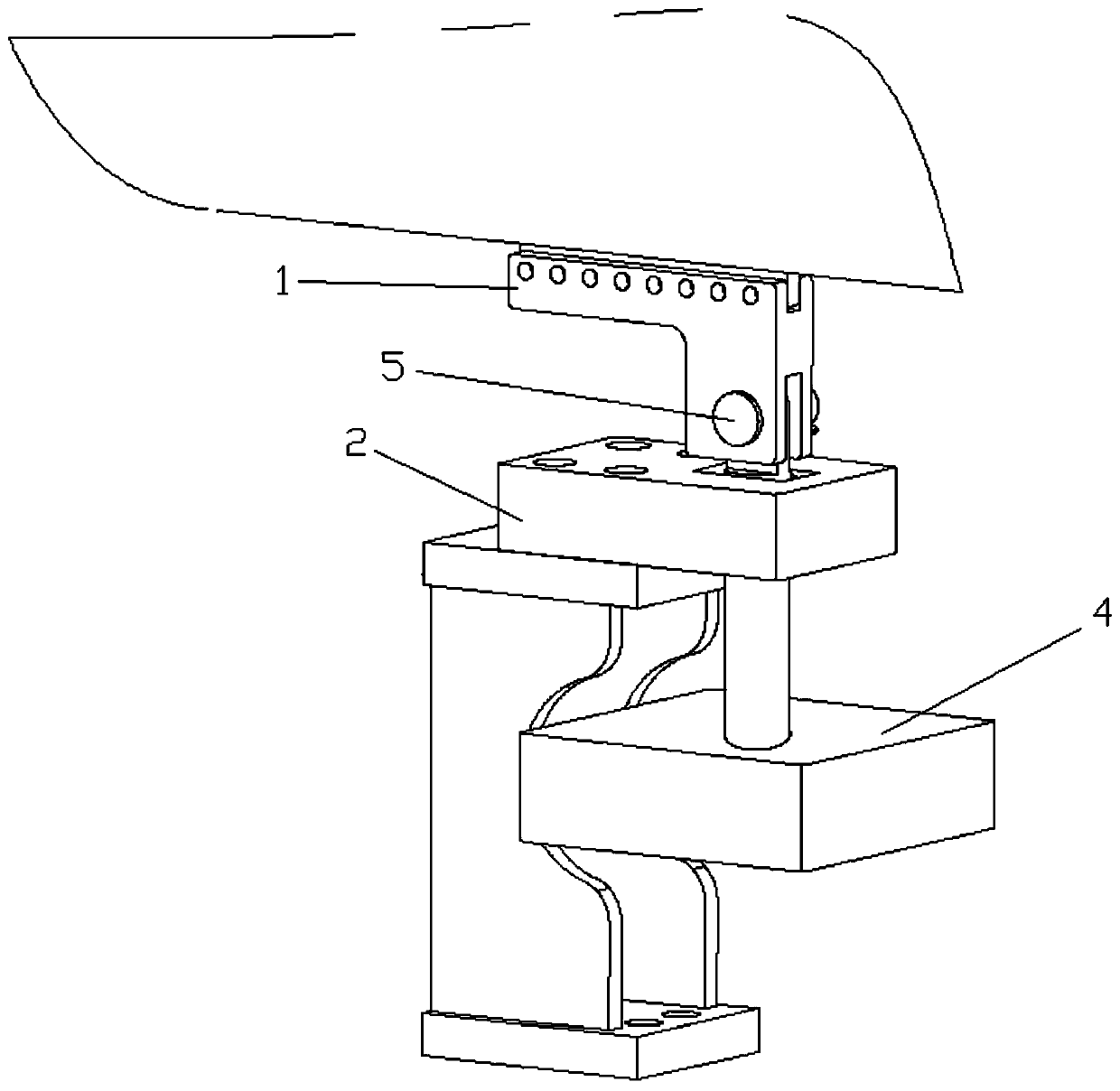
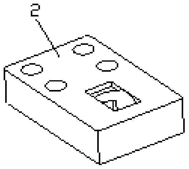
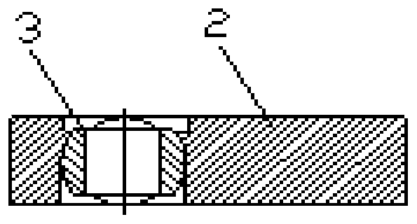
The invention belongs to the field of designs of engine supporting structures and in particular relates to an axial anti-impacting device. The axial anti-impacting device comprise a rotary connectionbody, a fixed seat, a spherical ring and a swinging part, wherein the top of the rotary connection body is connected with an engine case; the fixed seat is provided with a square through hole; the bottom of the fixed seat is connected to a rack base; the spherical ring is provided with a first through hole which penetrating through a spherical center; the spherical ring is rotatably clamped in thesquare through hole of the fixed seat; the swinging part comprises a heavy hammer and a swinging rod; and one end of the swinging rod penetrates through a first through hole of the spherical ring andis hinged to the bottom of the rotary connection body, wherein the distance between the rotary connection body and the spherical ring is shorter than the distance between the spherical ring and the heavy hammer. The axial anti-impacting device provided by the invention is simple in structure; axial impact is effectively absorbed and heat expansion also can be absorbed; and an axial force and thermal stress are balanced and the problem of stress concentration is solved.

Description

technical field [0001] The application belongs to the field of engine support structure design, and in particular relates to an axial anti-shock device. Background technique [0002] In the support system structure of the gas turbine main engine, two structural forms of main support two points and auxiliary support two points are usually adopted. [0003] Form 1. The upper end of the main support is hinged, and the lower end is rigidly fixed. The engine can only rotate along the center line connecting the two main fulcrums, and the upper and lower ends of the auxiliary support are both hinged. In the event of impact, the main support can bear axial, vertical, and lateral forces, and the auxiliary support can only bear vertical force. When thermal expansion occurs, the main fulcrum is fixed, and the auxiliary support can move freely in the axial and lateral directions. The disadvantage is: in the case of axial impact, only the main support can bear the force, and the auxilia...

Claims


Application Information

Patent Timeline
Patent Type & Authority Patents(China)
IPC IPC(8): F02C7/20
Inventor 张东林任立新王泠
Owner AECC SHENYANG ENGINE RES INST
Learn More