
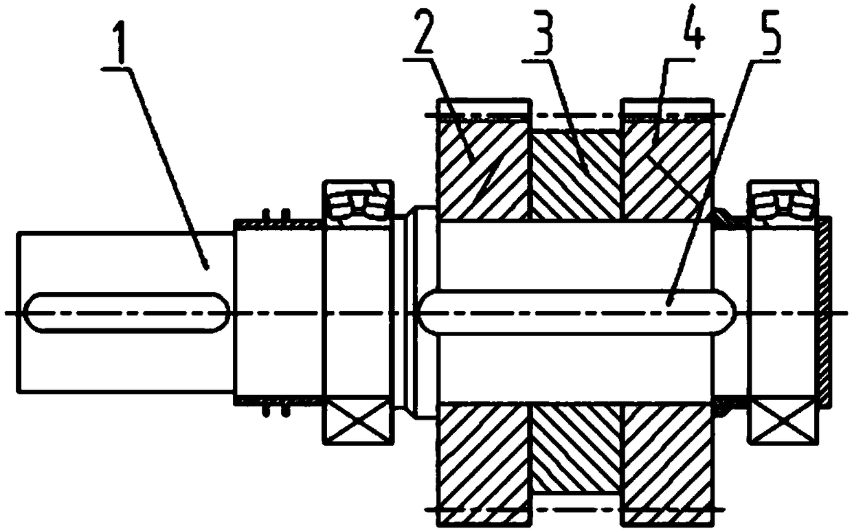
Combined type herringbone gear structure

A herringbone gear, combined technology, applied in belts/chains/gears, components with teeth, portable lifting devices, etc., can solve the problems of gear hobbing and gear grinding with limited weight, high equipment requirements, and increased cost. , to achieve the effect of more choices of processing machine tools, flexible processing methods and saving processing time

Inactive Publication Date: 2019-01-11
扬州市轩煌铸造有限公司
View PDF0 Cites 0 Cited by
  • Summary
  • Abstract
  • Description
  • Claims
  • Application Information

AI Technical Summary

Problems solved by technology

[0002] At present, most of the herringbone gears on the market are formed by integral forging, which can be used when the diameter is relatively small, but if the integral type is used for large diameters, first, the weight of the forging is very large, and the cost is very high. Second, gear hobbing, grinding The bearing weight of the teeth is limited, and the integral herringbone gear hobbing and gear grinding need to find a much larger machine tool, the cost increases, and the processing equipment does not necessarily require outsourcing
The left-handed gear and the right-handed gear of the shaft of the herringbone gear form herringbone teeth and are located in the middle of the shaft. The distance between the two teeth is at most only the undercut. High equipment requirements

Method used


Image

  • Combined type herringbone gear structure

Examples


Embodiment Construction

[0011] In order to make the objectives, technical solutions, and advantages of the present invention clearer, the following further describes the present invention with reference to the accompanying drawings and specific embodiments. It should be understood that the specific embodiments described here are only used to explain the present invention, but not to limit the present invention. Based on the embodiments of the present invention, all other embodiments obtained by those of ordinary skill in the art without creative work shall fall within the protection scope of the present invention. The present invention will now be described in further detail with reference to the drawings. These drawings are all simplified schematic diagrams, which merely illustrate the basic structure of the present invention in a schematic manner, so they only show the structures related to the present invention.

[0012] Such as figure 1 As shown, a combined herringbone gear structure includes a ro...


PUM


Abstract

The invention relates to a combined type herringbone gear structure. The combined type herringbone gear structure comprises a shaft, a right-handed rotation single helical gear and a left-handed rotation single helical gear. The rotation direction of the right-handed rotation single helical gear is opposite to that of the left-handed rotation single helical gear. The combined type herringbone gearstructure further comprises a distance ring which is arranged between the right-handed rotation single helical gear and the left-handed rotation single helical gear. The right-handed rotation singlehelical gear, the left-handed rotation single helical gear and the distance ring are in cooperative connection with the shaft through keys. According to the combined type herringbone gear structure, split-type forging can be adopted, the machining method is flexible, more machining tools can be selected, machining time is saved, and the cost is reduced.

Description

Technical field [0001] The invention relates to the technical field of speed reducers, in particular to a combined herringbone gear structure. Background technique [0002] At present, most herringbone gears on the market are formed by integral forging, which can be used when the diameter is relatively small, but if the integral type is used when the diameter is large, the weight of the forging is very large and the cost is very high, and the second is gear hobbing and grinding. The weight of the tooth is limited. The integral herringbone gear hobbing and grinding need to find a much larger machine tool, the cost is higher, and the processing equipment does not necessarily need to be outsourced. The left-handed gear and the right-handed gear of the herringbone gear shaft form herringbone teeth and are located in the middle of the shaft. The distance between the two teeth is only undercut. The assembly method of this structure is difficult in the assembly process, and the cost inc...

Claims


Application Information

Patent Timeline
Patent Type & Authority Applications(China)
IPC IPC(8): F16H55/17F16H55/06
CPCF16H55/17F16H55/06F16H2055/065
Inventor 郑生龙
Owner 扬州市轩煌铸造有限公司
Learn More