
Non-checkerboard-pattern calibration plate for calibrating white light scanner

A technology for calibrating plates and scanners, applied in the field of visual measurement, can solve the problems of high layout density, prone to errors, and interfere with the imaging quality of photos, and achieve the effects of improving imaging quality, reducing errors, and strong operability.

Inactive Publication Date: 2019-01-11
宣城镐渭工业技术有限公司
View PDF0 Cites 2 Cited by
  • Summary
  • Abstract
  • Description
  • Claims
  • Application Information

AI Technical Summary

Problems solved by technology

[0004] The black and white grids on the traditional checkerboard calibration board have a high layout density, and the imaging effect is not ideal. The discontinuous white gaps in the checkerboard will seriously interfere with the imaging quality of the photo, resulting in the calibration accuracy of the visual measurement imaging system. significantly reduce
In addition, the characteristic information of each marker point is the same, and errors are prone to occur when the scanner is calibrated. Generally, the pattern of the entire calibration plate needs to be placed in the scanner’s field of view to perform data calibration; the image of the marker points in the calibration plate lacks detailed information. , the matching accuracy with the built-in pixel coordinates of the scanner is not high

Method used


Image

  • Non-checkerboard-pattern calibration plate for calibrating white light scanner
  • Non-checkerboard-pattern calibration plate for calibrating white light scanner
  • Non-checkerboard-pattern calibration plate for calibrating white light scanner

Examples


Embodiment

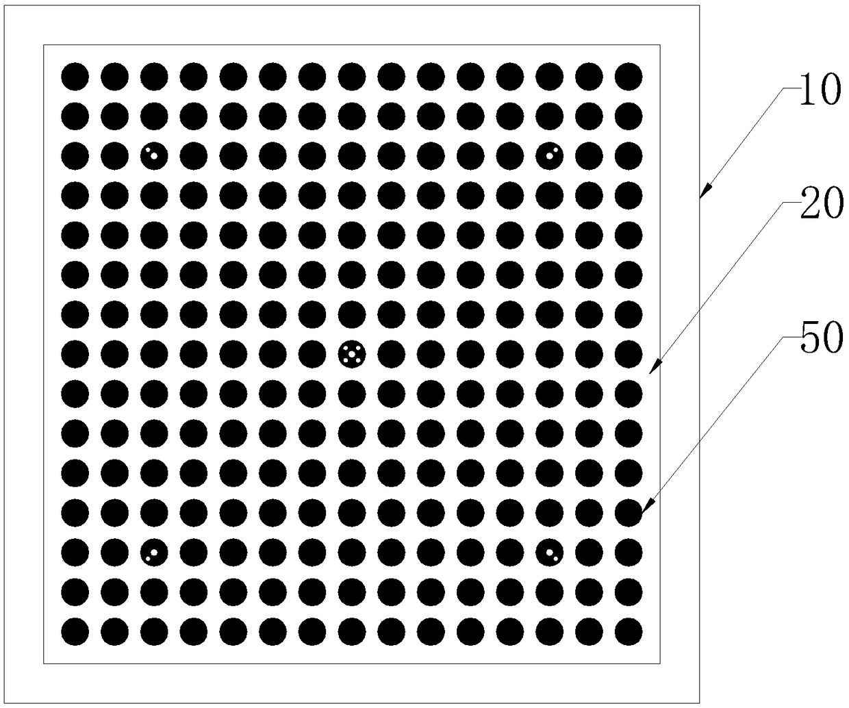
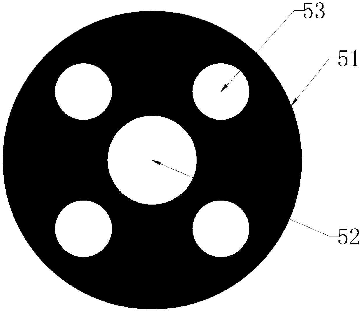
[0023] A non-checkerboard format calibration plate for white light scanner calibration, comprising a light-shielding back plate 10 and a light-transmitting calibration plate 20, the center of the back plate is provided with a cavity 30 with an opening, and the cavity 30 A luminous plate 40 is fixed inside, and the calibration plate 20 is fixed at the opening of the cavity 30. On the surface of the calibration plate 20, there are rectangular arrays of marking circles 50 of the same size. Among the marking circles 50 of the rectangular array are A positioning circle 51 is provided, a central circle 52 is provided at the center of the positioning circle 51 , and at least one auxiliary circle 53 is provided beside the central circle 52 .

[0024] Wherein, the size of each sign circle 50 is the same, and the distance of adjacent sign circles 50 is the same, the positioning circle 51 that is set in the sign circle 50 has inner central circle 52 and auxiliary circle 53 distinguishing ...


PUM


Abstract

The invention discloses a non-checkerboard-pattern calibration plate for a calibrating white light scanner. The non-checkerboard-pattern calibration plate comprises a backboard and a calibration plate, wherein a cavity with an opening is formed in the center of the backboard, a light-emitting plate is fixedly arranged in the cavity, the calibration plate is fixedly arranged at the opening of the cavity, marker circles with the same size are arranged on the surface of the calibration plate in an rectangular array manner, positioning circles are arranged in the marker circles, central circles are arranged in the centers of the positioning circles, and at least one auxiliary circle is arranged beside the central circles. According to the non-checkerboard-pattern calibration plate, positioningcircles are arranged in the rectangular-arrayed marker circles, and each positioning circle has unique parameter information, so that the calibration of the position is conveniently finished; the calibration plate is produced from a light-transmission material, and the marker circles are produced from a light-shading coating, so that a high-contrast calibration plate is formed, and errors are reduced; the positioning circles are few; and by aligning the scanner with any one positioning circle, coordinate information can be calculated, and the corresponding position calibration can be finished, so that the calibration plate has relatively strong operability and is relatively convenient.

Description

technical field [0001] The invention relates to the technical field of visual measurement, in particular to a non-chessboard calibration plate used for calibration of white light scanners. Background technique [0002] In the field of machine vision and photogrammetry, the main equipment to complete the measurement task is the scanner. Accurate calibration of the scanner parameters is the prerequisite for the completion of the measurement task. The calibration board is a calibration tool that technicians in the field often use. , image measurement, photogrammetry, 3D reconstruction and other applications, it can be used to correct the lens distortion of the camera. [0003] The calibration boards in the prior art generally have two types of checkerboard format and solid circles. The checkerboard grid and solid circles are used as marking points. Shoot, obtain the image of the calibration plate, and calculate the image to obtain the calibration data. [0004] The black and ...

Claims


Application Information

Patent Timeline
IPC IPC(8): G01C25/00
CPCG01C25/00
Inventor 林青杨贤亮
Owner 宣城镐渭工业技术有限公司
Learn More