Fine adjustment device, detection system and detection method used for ray non-nondestructive detection

A non-destructive testing and fine-tuning device technology, applied in measurement devices, material analysis using wave/particle radiation, instruments, etc., can solve the problems of deviation from the ideal rotation center, inconvenient operation, low efficiency, etc., and achieve the effect of improving detection accuracy.

Pending Publication Date: 2019-01-11
SHANGHAI MUSEUM +1
View PDF8 Cites 5 Cited by
  • Summary
  • Abstract
  • Description
  • Claims
  • Application Information

AI Technical Summary

Problems solved by technology

[0005] At present, when the existing CT detection system scans the object to be inspected, in order to make full use of the detection range of the detector and detect multiple positions of the object to be inspected, it is necessary to adjust the position of the object to be inspected on the rotating table of the CT equipment. Adjust the position of the object to be inspected so that the detection position of the object to be inspected is within the center of the detection ray as much as possible. This method is very difficult to operate due to repeated switching on and off the ray to check the position of the object to be inspected and repeatedly entering the lead room to manually adjust the position of the object to be inspected. Inconvenient and inefficient, but if the rotating platform is directly adjusted, the system rotation center is not in the ideal position, making the actual control system center deviate from the ideal rotation center, that is, the actual rotation center deviates from the reconstruction rotation center, which not only deforms the reconstruction image , and produce dotted line edges, etc., which reduce the image clarity, thereby reducing the detection accuracy of the CT detection system

Method used


Image

  • Fine adjustment device, detection system and detection method used for ray non-nondestructive detection
  • Fine adjustment device, detection system and detection method used for ray non-nondestructive detection
  • Fine adjustment device, detection system and detection method used for ray non-nondestructive detection

Examples


Embodiment

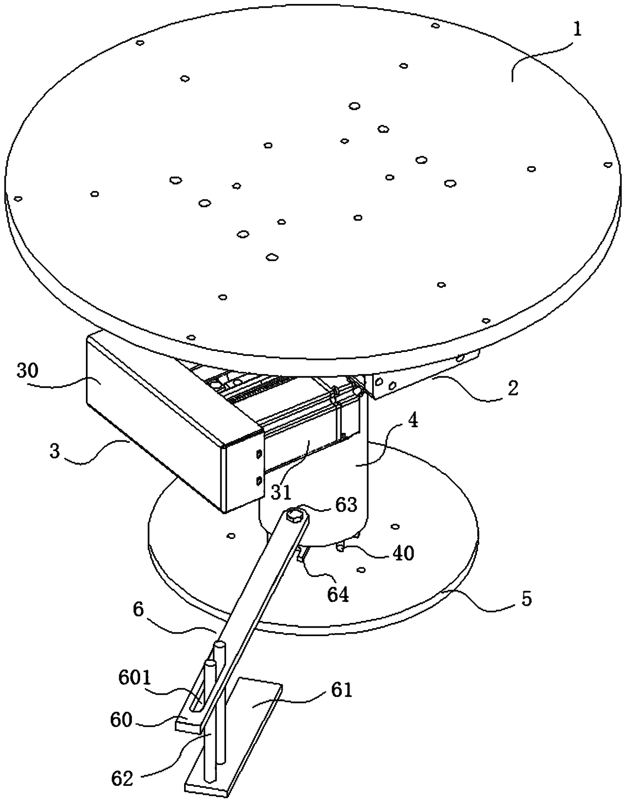
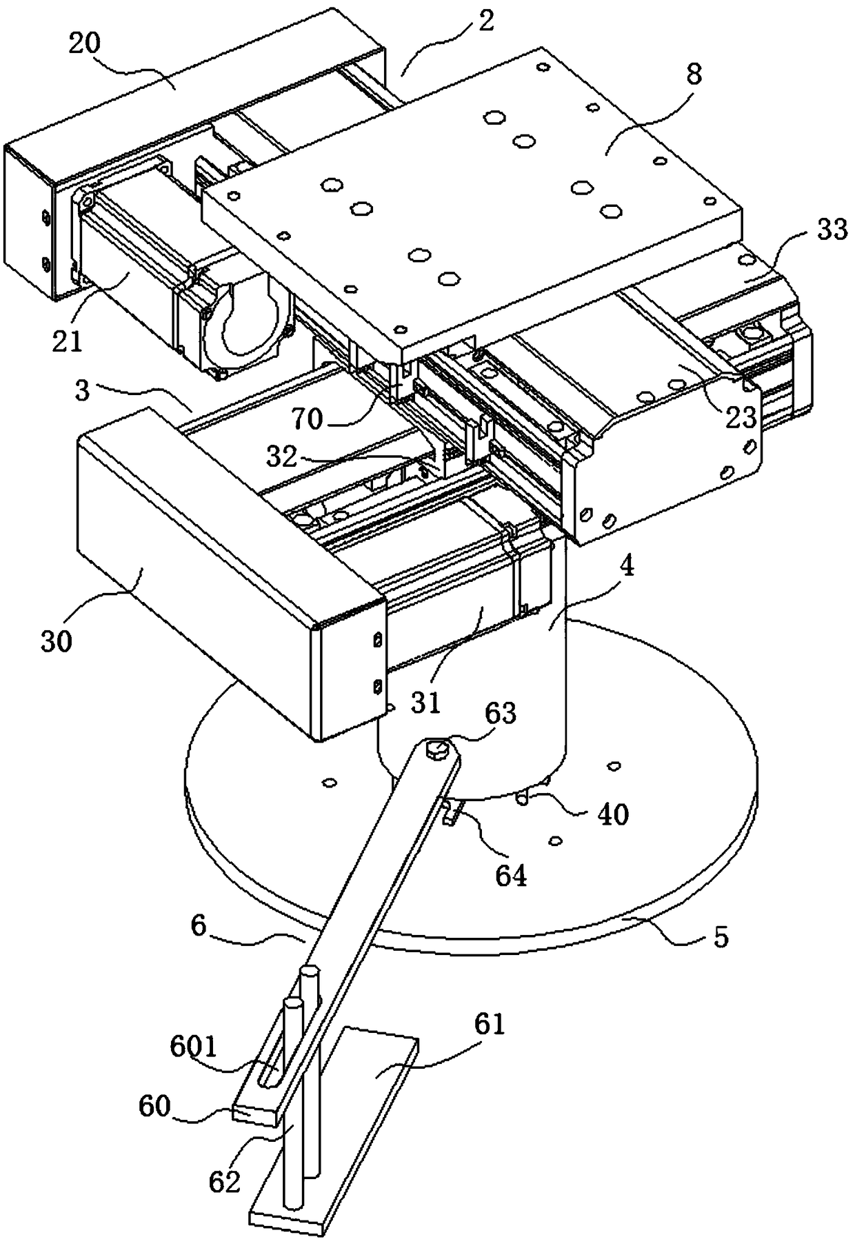
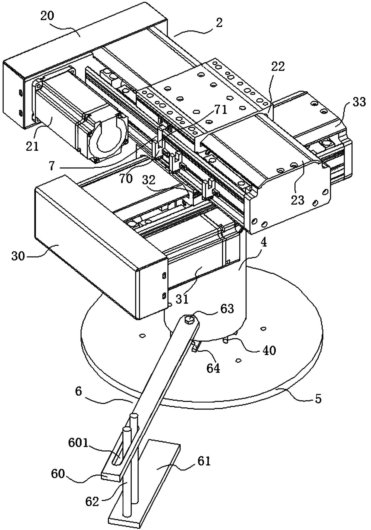
[0031] like Figure 1 to Figure 5 As shown, this embodiment provides a fine-tuning device for ray nondestructive testing, and a fine-tuning device for ray non-destructive testing, including: a stage 1 for placing an object to be inspected; an X-axis fine-tuning mechanism 2, Connected to the lower end of the stage 1, used to move the stage 1 along the X-axis direction; The position of stage 1.

[0032] Specifically, in this embodiment, a fine-tuning device for ray non-destructive testing is added to the existing industrial CT equipment, and an intelligent PLC control program is added on the basis of the existing industrial CT control system. There is a one-key reset button, an anti-misoperation button, etc., the position of the object to be inspected is adjusted by a fine-tuning device; it ensures that the operator is convenient, fast and error-free during operation. The control panel is located in the inspection room, away from the radiation area of ​​industrial CT. The runn...


PUM


Abstract

The invention provides a fine adjustment device, a detection system and a detection method used for ray non-nondestructive detection. The device comprises an objective table for placing a to-be-detected object, an X-axis fine adjustment mechanism connected at a lower end of the objective table and used for moving the objective table along an X-axis direction, and a Y-axis fine adjustment mechanismconnected at the lower end of the X-axis fine adjustment mechanism and used for moving the X-axis fine adjustment mechanism along a Y-axis direction to change a position of the objective table. According to the fine adjustment device, the detection system and the method provided by the invention, based on that the fine adjustment device is mounted on a turn table of the detection system, the position of the to-be-detected object is adjusted finely, a detection position of the to-be-detected object is enabled to be located around a center of a detection ray as much as possible, consequently, satisfying a condition where a rotation center, a detector center and a ray source focus are in the same straight line in a projection and reconstruction process of a CT system is facilitated, and optimal geometric magnification ratio can be obtained quickly, and detection precision of the CT detection system is improved.

Description

technical field [0001] The invention relates to the technical field of industrial CT non-destructive testing equipment, in particular to a fine-tuning device, a detection system and a method for ray non-destructive testing. Background technique [0002] Industrial CT is a non-destructive testing technology that reconstructs the two-dimensional cross-sectional view and three-dimensional structure of an object through projection data. It can intuitively, clearly and accurately display the material organization structure and material density distribution inside the object, and measure the internal size of the object through the displayed image. , defect detection, three-dimensional reverse design. It is widely used in various industries such as automobiles, geological exploration, petroleum exploration, aerospace, cultural relics detection, industrial manufacturing workpieces, etc. [0003] The industrial CT non-destructive testing system is based on radiation imaging technolo...

Claims


Application Information

Patent Timeline
Patent Type & Authority Applications(China)
IPC IPC(8): G01N23/046
CPCG01N23/046
Inventor 武慧唐起波
Owner SHANGHAI MUSEUM
Why Eureka
Try Eureka