Pure surface three-dimensional observation system suitable for high-speed rail tunnel bottom earthquake CT

An observation system and tunnel bottom technology, applied in the fields of seismology, seismic signal processing, geophysical measurement, etc., can solve the problems of not allowing drilling, destructive damage to the surface of the tunnel bottom, unsuitable for seismic observation of the tunnel bottom, etc. Broad application prospects and significant effects

Inactive Publication Date: 2019-01-11
中铁科学研究院有限公司
View PDF0 Cites 10 Cited by
  • Summary
  • Abstract
  • Description
  • Claims
  • Application Information

AI Technical Summary

Problems solved by technology

[0002] At present, the existing technologies commonly used in the industry are as follows: conventional seismic CT technology is generally cross-hole CT between wells, and usually two-dimensional CT detection, but for high-speed rail tunnel bottom seismic CT, due to the high-speed rail tunnel after construction Due to the particularity of the tunnel bottom structure, drilling is not allowed in principle, nor is destructive damage to the surface of the tunnel bottom allowed, so conventional methods cannot be applied
[0003] To sum up, the problems existing in the existing technology are: the conventional seismic CT technology is generally cross-hole CT between wells, and usually two-dimensional CT detection, it is impossible to realize three-dimensional seismic observation without drilling Suitable for seismic observation at the bottom of tunnels
[0004] The difficulty and significance of solving the above technical problems: Difficulty: 1. So far, it is impossible to carry out seismic CT detection of railway tunnels without drilling, and neither 2D seismic CT nor 3D seismic CT can be realized; 2. , This is not only a problem of observation methods, but also involves the corresponding data processing methods and software problems

Method used


Image

  • Pure surface three-dimensional observation system suitable for high-speed rail tunnel bottom earthquake CT
  • Pure surface three-dimensional observation system suitable for high-speed rail tunnel bottom earthquake CT
  • Pure surface three-dimensional observation system suitable for high-speed rail tunnel bottom earthquake CT

Examples


Embodiment Construction

[0039] In order to make the object, technical solution and advantages of the present invention more clear, the present invention will be further described in detail below in conjunction with the examples. It should be understood that the specific embodiments described here are only used to explain the present invention, not to limit the present invention.

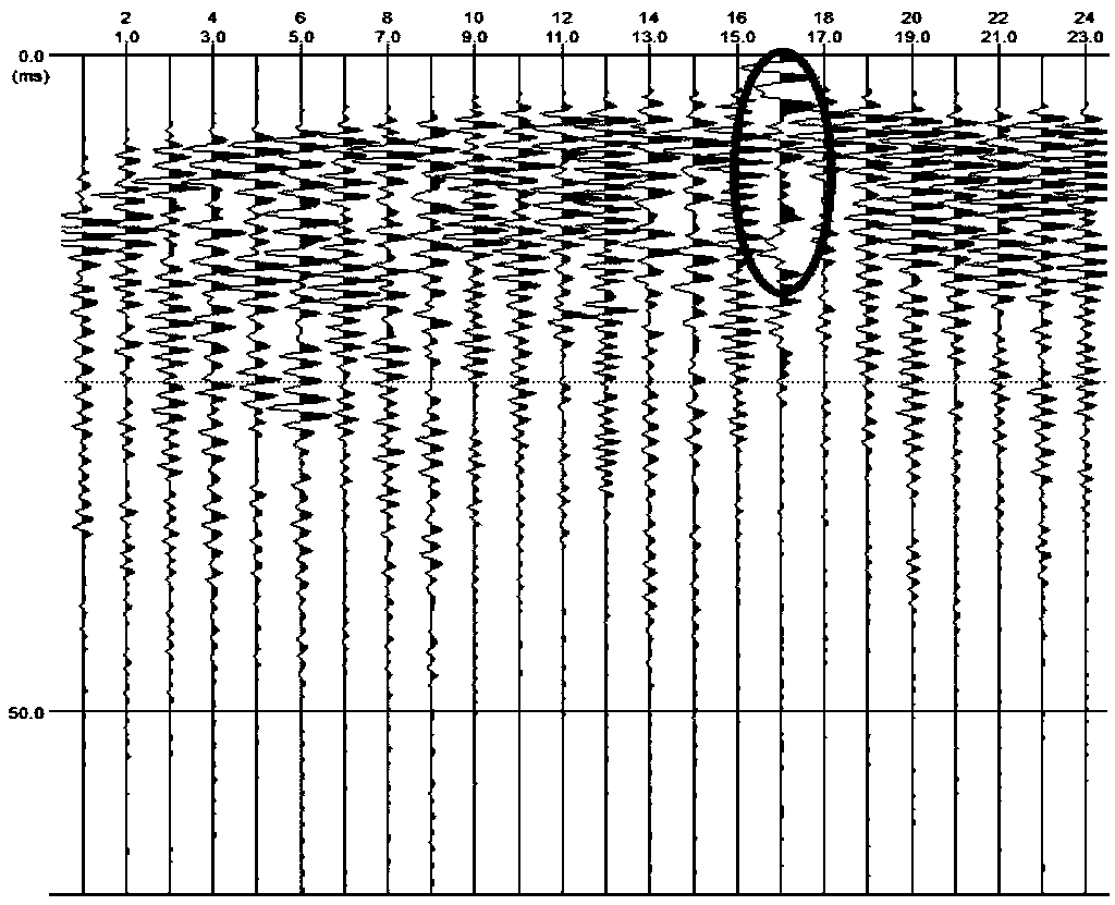
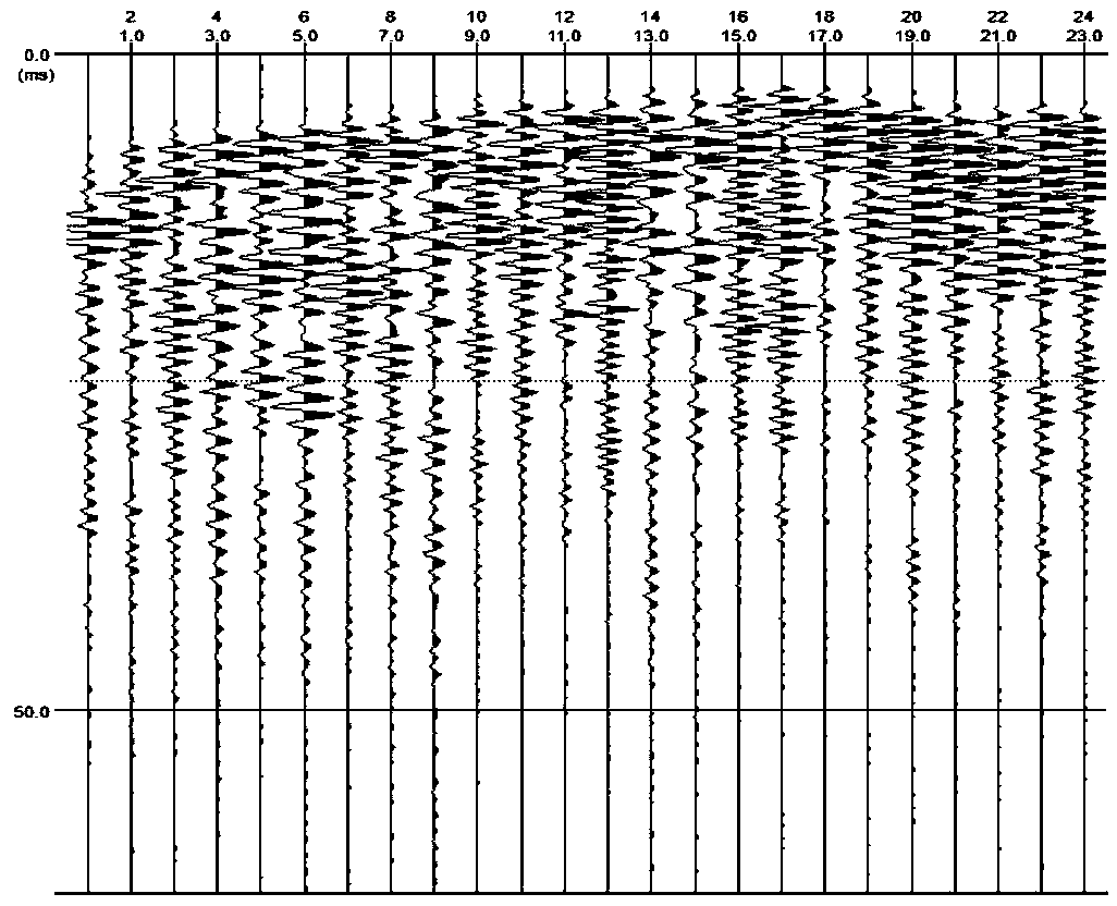
[0040] The application principle of the present invention will be described in detail below in conjunction with the drawings and animations.

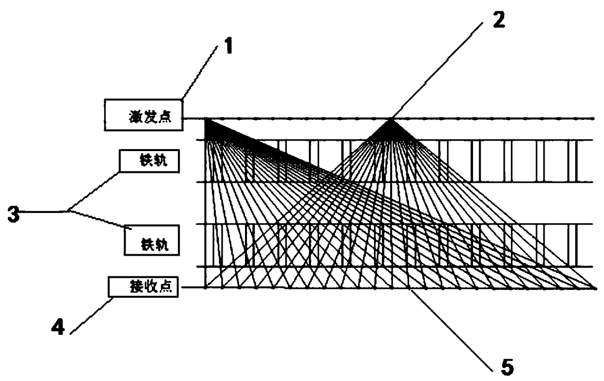
[0041] Such as figure 1 As shown, the pure surface three-dimensional observation system suitable for high-speed railway tunnel bottom seismic CT provided by the embodiment of the present invention includes: a first excitation point (i.e., the seismic source) 1, a second excitation point (i.e., the seismic source) 2, a rail 3, and a first detection device (receiving point) 4, second wave detector (receiving point) 5.

[0042] The source point 1 is set on one side of the rail 3, and th...


PUM


Abstract

The invention belongs to the technical field of three-dimensional earthquake CT, and discloses a pure surface three-dimensional observation system suitable for high-speed rail tunnel bottom earthquakeCT. An earthquake source point is arranged on one side of the rail, and a receiving point is arranged on the other side of the rail. An earthquake wave is excited by the earthquake source point and passes through a tunnel bottom medium to enter the receiving point so as to receive an earthquake signal. The pure surface three-dimensional observation system disclosed by the invention can not only achieve three-dimensional fine detection of the tunnel bottom structure, but also can greatly reduce the exploration cost of the tunnel bottom detection; after once excitation of 24 excitation points arranged at equal intervals in the observation system, each wave detection point can receive 24 data, and the total data volume is 24*24=576, which is much higher than the 24 data of one array of the conventional two-dimensional detection, so that the fluctuation information amount of an underground geological body is greatly improved, the detection accuracy is greatly improved, and pure surface three-dimensional CT detection,that is, three-dimensional CT detection without drilling, is realized for the three-dimensional underground space data; and the exploration cost of the tunnel bottom detection is greatly reduced.

Description

technical field [0001] The invention belongs to the technical field of three-dimensional seismic detection methods and seismic data processing, and in particular relates to a pure surface three-dimensional observation system suitable for high-speed railway tunnel bottom seismic CT. Background technique [0002] At present, the existing technologies commonly used in the industry are as follows: conventional seismic CT technology is generally cross-hole CT between wells, and usually two-dimensional CT detection, but for high-speed rail tunnel bottom seismic CT, due to the high-speed rail tunnel after construction Due to the particularity of the tunnel bottom structure, drilling is not allowed in principle, nor is destructive damage to the surface of the tunnel bottom allowed, so conventional methods cannot be applied. [0003] To sum up, the problems existing in the existing technology are: the conventional seismic CT technology is generally cross-hole CT between wells, and us...

Claims


Application Information

Patent Timeline
Patent Type & Authority Applications(China)
IPC IPC(8): G01V1/00G01V1/20G01V1/28
CPCG01V1/00G01V1/20G01V1/28
Inventor 蒋正红魏成武宋振东胡辉荣张腾飞魏燃王丹宋斌张武洪汪明春潘明亮李若男徐仁中夏龙龙黎佳宾
Owner 中铁科学研究院有限公司
Why Eureka
Try Eureka