

Closed type display plasma module and manufacturing method thereof
A manufacturing method and a closed technology, applied in electrode system manufacturing, discharge tube/lamp manufacturing, cold cathode manufacturing, etc., to achieve the effects of improving contrast, reducing manufacturing costs, and ensuring directivity and verticality
- Summary
- Abstract
- Description
- Claims
- Application Information
AI Technical Summary
Problems solved by technology
Method used
Image

Examples
Embodiment Construction
[0038] The present invention will be further described below in conjunction with specific drawings and embodiments.
[0039] The present invention is not limited to the following embodiments, and the figures referred to in the following description are provided for understanding the content of the present invention, that is, the present invention is not limited to the structure of the electronic ink display screen exemplified in each figure.
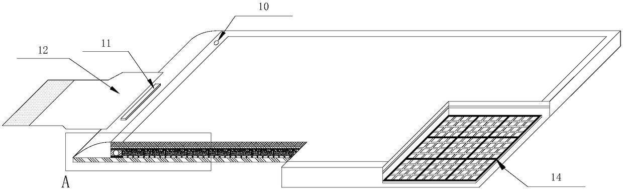
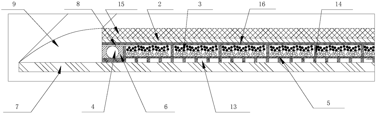
[0040] as attached figure 1 and figure 2 As shown, Embodiment 1 takes a dual-particle electronic ink display screen as an example. A closed display plasma module includes a pixel electrode 13 and a transparent electrode 1 located above the pixel electrode 13. The pixel electrode 13 and the transparent electrode 1 The display plasma 3 and the liner frame 6 surrounding the display plasma 3 are arranged between them; the pixel electrode 13 is provided with a plasma barrier array 14 for uniformly dispersing and stabilizing the display plas...
PUM
| Property | Measurement | Unit |
|---|---|---|
| Border width | aaaaa | aaaaa |
| Width | aaaaa | aaaaa |
| Viscosity | aaaaa | aaaaa |
Abstract
Description
Claims
Application Information