
An automatic failure switching device for a mainframe computer server

A large-scale computer and automatic switching technology, applied in the computer field, can solve the problems of inability to switch data, inability to monitor faults in real time, and low efficiency

Inactive Publication Date: 2019-01-11
CHONGQING COLLEGE OF ELECTRONICS ENG
View PDF0 Cites 0 Cited by
  • Summary
  • Abstract
  • Description
  • Claims
  • Application Information

AI Technical Summary

Problems solved by technology

Since the computer server is composed of multiple independent electronic devices, its computing power is also based on the function of each electronic device. Due to the use environment or the quality of the product itself, after a long period of operation, the computer server will inevitably fail. Various failures will occur, and the existing devices cannot monitor the failures in real time, and cannot automatically switch data, and the efficiency is relatively low

Method used


Image

  • An automatic failure switching device for a mainframe computer server
  • An automatic failure switching device for a mainframe computer server
  • An automatic failure switching device for a mainframe computer server

Examples


Embodiment 1

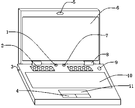
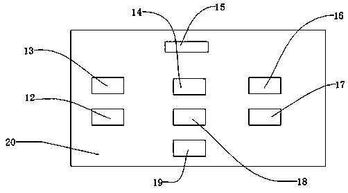
[0045] Such as Figure 1-Figure 11As shown, a kind of failure automatic switching device for large-scale computer server, comprises display screen 6, keyboard 10, circuit board 20, and display screen 6 top is provided with camera 5, and display screen 6 bottom is provided with rotating shaft 8, and rotating shaft 8 One side is provided with a circuit board 20, the upper part of the circuit board 20 is provided with a casing 21, one side of the circuit board 20 is provided with a power interface 3, the front part of the circuit board 20 is provided with a speaker 2, and one side of the speaker 2 is provided with a fault indicator light 1, normal The working indicator light 7, the speaker 2 side is provided with the switch key 9, the speaker 2 bottom is provided with the keyboard 10, the keyboard 10 bottom is provided with the touchpad 11, the touchpad 11 bottom is provided with the pressing key 4, and the front of the circuit board 20 is provided with State real-time monitoring...

Embodiment 2

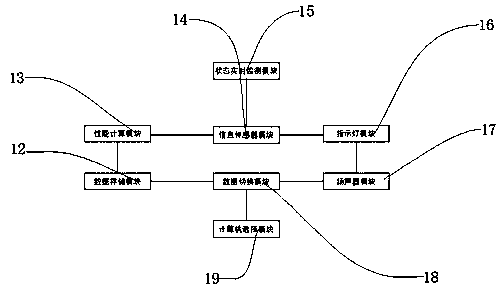
[0048] The difference between this embodiment and Embodiment 1 is that in this embodiment, the performance calculation module 13 is connected to the circuit board 20 by welding, the data storage module 12 is connected to the circuit board 20 by welding, and the information sensor module 14 is connected to the circuit board 20 by welding. On the circuit board 20 , the data switching device 18 is connected to the circuit board 20 by soldering. Specifically, such setting can realize real-time monitoring of faults by the computer, greatly reduce human labor, realize automatic switching of fault data, and improve work efficiency.

[0049] Further, in the real-time status monitoring device 15, the computer 22 is connected to the base 31 by screws, the second display screen 23 is connected to the computer 22 by screws, and the electric wire 24 is connected to the computer 22 and the computer power supply 25 by plugging. connection so that the computer 22 is stably fixed on the base 3...

Embodiment 3

[0054] The difference between this embodiment and Embodiment 1 is:

[0055] In the state real-time monitoring device 15, the computer power supply 25 is connected with the monitoring box 26 by screws, the wireless modem 27 is connected with the monitoring box 26 by screws, the antenna 28 is connected with the wireless modem 27 screws, and the shunt 29 is connected with the monitoring box 26. Screw connection, the data bus 30 is connected with the shunt 29 and the computer 22 by plugging, so that the computer power supply 25 is stably fixed on the monitoring box 26, so that the wireless modem 27 is stably fixed on the monitoring box 26, so that the antenna 28 It is stably fixed on the wireless modem 27 so that the shunt 29 is stably fixed on the monitoring box 26 so that the computer 22 can transmit data to the monitoring box 26.


PUM


Abstract

The invention discloses a failure automatic switching device for a mainframe computer server, the device including a display, a keyboard, and a circuit board. A camera is arranged on the upper part ofthe display screen, a lower part of that display screen is provided with a rotation shaft, a circuit board is arranged on one side of the rotation shaft, an upper part of that circuit board is provided with a shell, a power supply interface is arranged on one side of the circuit board, a loudspeaker is arranged at that front part of the circuit board, a fault indicator lamp and a normal working indicator lamp are arranged at one side of the loudspeaker, a switch key is arranged at the other side of the loudspeaker, a keyboard is arranged at the lower part of the loudspeaker, a touch panel isarranged at the lower part of the keyboard, and a pressing key is arranged at the lower part of the touch panel. The failure automatic switching device has the advantages that: 1, the computer realizes the real-time monitoring of the faults and greatly reduces the human labor; 2, the automatic switch of fault data is realized, and the work efficiency is improved.

Description

technical field [0001] The invention relates to the field of computer technology, in particular to an automatic failover device for a large computer server. Background technique [0002] As a product of the information age, the computer's ability to process digital information has become stronger with the advancement of technology. General computers are divided into personal computers and enterprise computers. Personal computers are simple in structure and are mainly composed of hosts, monitors and external devices. They can be connected to LAN or WAN through network cards; enterprise computers usually have a large number of independent computers and connections to these computers. The composition of the server, between the computer and the server - a local area network, information can be freely transmitted in this local area network without restriction. Since the computer server is composed of multiple independent electronic devices, its computing power is also based on t...

Claims


Application Information

Patent Timeline
Patent Type & Authority Applications(China)
IPC IPC(8): G06F11/30G06F11/32H04L12/02H04L12/24
CPCG06F11/3006G06F11/3058G06F11/327H04L12/02H04L41/0663
Inventor 林勇
Owner CHONGQING COLLEGE OF ELECTRONICS ENG
Learn More