Manufacturing method of flexible liquid crystal display device

A flexible liquid crystal display and manufacturing method technology, which is applied in identification devices, nonlinear optics, optics, etc., can solve the problems that display devices cannot meet the designer's requirements for product shape, residue, glass substrate thickness, etc.

Active Publication Date: 2019-01-11
SHENZHEN AV DISPLAY
View PDF10 Cites 5 Cited by
  • Summary
  • Abstract
  • Description
  • Claims
  • Application Information

AI Technical Summary

Problems solved by technology

[0002] The current LCD display devices basically use glass substrates as substrates. Display devices based on glass substrates cannot meet the designer's requirements for product shape in many cases due to their inability to bend. Moreover, glass substrates are generally thick, and are subject to pressure or impact. easy to break after
[0003] The traditional flexible LCD production process uses double-sided adhesive to attach the flexible conductive film to the glass substrate. However, the double-sided adhesive is generally only attached to the edge area of ​​the flexible conductive film, so that the middle area of ​​the flexible conductive adhesive cannot be completel

Method used


Image

  • Manufacturing method of flexible liquid crystal display device
  • Manufacturing method of flexible liquid crystal display device
  • Manufacturing method of flexible liquid crystal display device

Examples


Embodiment 1

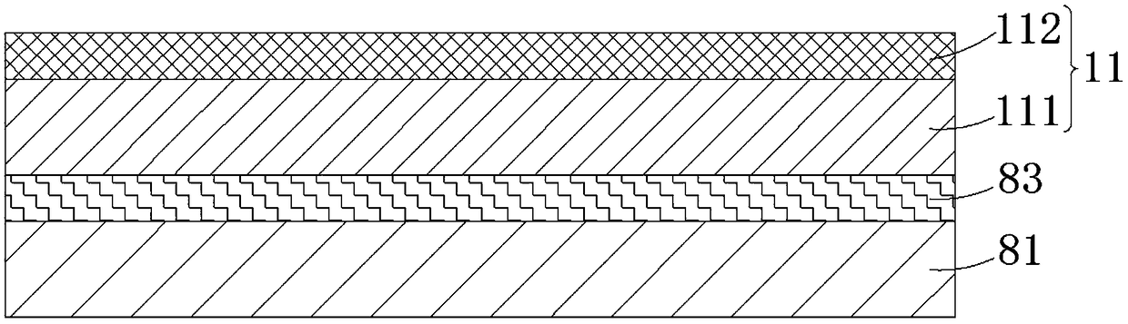
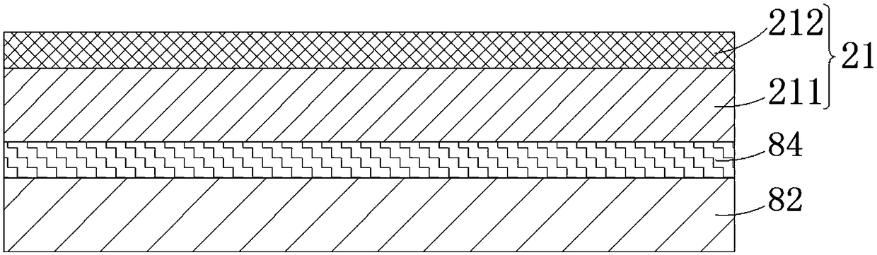
[0072] see Figure 2A to Figure 9 , the embodiment 1 provides a method for manufacturing a flexible liquid crystal display device, comprising:

[0073] Step 1, such as Figure 1A and Figure 1B As shown, a first flexible conductive film 11 , a second flexible conductive film 21 , a first rigid substrate 81 , a second rigid substrate 82 , a first UV peelable adhesive film 83 and a second UV peelable adhesive film 84 are provided.

[0074] The first flexible conductive film 11 includes a first flexible substrate 111 and a first conductive layer 112 disposed on the first flexible substrate 111, and the second flexible conductive film 21 includes a second flexible substrate 211 and The second conductive layer 212 is disposed on the second flexible substrate 211 .

[0075] The first UV peelable adhesive film 83 and the second UV peelable adhesive film 84 all have double-sided adhesiveness, and the first UV peelable adhesive film 83 and the second UV peelable adhesive film 84 all ...

Embodiment 2

[0133] see Figure 10A to Figure 10D , see also Figure 2A to Figure 9 , the embodiment 2 provides a method for manufacturing a flexible liquid crystal display device, comprising:

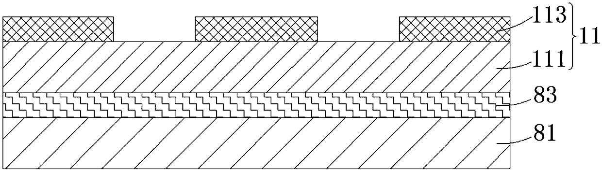
[0134] Step 1', such as Figure 10A , Figure 10B , Figure 10C as well as Figure 10D As shown, a first flexible conductive film 11 and a second flexible conductive film 21 are provided, and the first flexible conductive film 11 includes a first flexible substrate 111 and a first conductive layer disposed on the first flexible substrate 111 112 , the second flexible conductive film 21 includes a second flexible substrate 211 and a second conductive layer 212 disposed on the second flexible substrate 211 .

[0135] The first conductive layer 112 and the second conductive layer 212 are patterned respectively to obtain the first electrode 113 and the second electrode 213 .

[0136] The step 1' is completed on the reel production line, which is provided with an unwinding shaft and a rewinding sh...


PUM


Abstract

The invention discloses a manufacturing method of a flexible liquid crystal display device. By bonding the whole surface of the flexible conductive film to the hard substrate by using the UV strippable adhesive film before the bonding process, the liquid can be prevented from entering between the flexible conductive film and the hard substrate in the process of contacting with the liquid, and theliquid crystal cell thickness is prevented from being uneven due to bulging in the middle of the flexible conductive film in the heating process; By arranging the spacer particles with viscosity between the upper and lower substrates, the problem of cell thickness unevenness caused by the movement of the spacer particles when the flexible liquid crystal display device is bent or twisted can be avoided, and the quality and service life of the flexible liquid crystal display device can be improved.

Description

technical field [0001] The invention relates to the field of display technology, in particular to a method for manufacturing a flexible liquid crystal display device. Background technique [0002] The current LCD display devices basically use glass substrates as substrates. Display devices based on glass substrates cannot meet the designer's requirements for product shape in many cases due to their inability to bend. Moreover, glass substrates are generally thick, and are subject to pressure or impact. easy to break after. [0003] The traditional flexible LCD production process uses double-sided adhesive to attach the flexible conductive film to the glass substrate. However, the double-sided adhesive is generally only attached to the edge area of ​​the flexible conductive film, so that the middle area of ​​the flexible conductive adhesive cannot be completely attached to the glass substrate. When they are bonded together, there will be moisture remaining between the flexib...

Claims


Application Information

Patent Timeline
IPC IPC(8): G09F9/30G02F1/1339
CPCG02F1/13392G09F9/301
Inventor 吴梓荣王秋生杜华邹志明陈从心
Owner SHENZHEN AV DISPLAY
Why Eureka
Try Eureka