An inductor full-automatic and high-efficiency assembly device

An assembly equipment, fully automatic technology, applied in the direction of inductance/transformer/magnet manufacturing, circuits, electrical components, etc., can solve the problem of not being able to output one by one, and achieve the effect of saving external force output, increasing labor output, and ingenious structure

Inactive Publication Date: 2019-01-11
阜阳汇中芯自动化技术有限公司
View PDF12 Cites 3 Cited by
  • Summary
  • Abstract
  • Description
  • Claims
  • Application Information

AI Technical Summary

Problems solved by technology

[0005] The purpose of the present invention is to address the deficiencies of the prior art. By setting the stretching assembly of the wire flattening mechanism, the wires are transported backward one by one under the movement of the paddle blades, and then the twisted wires during the transportation are twisted by the pull-out parts. The wires are straightened, thus solving the technical problem that the wires cannot be output one by one when the wires are working on the upper body.

Method used


Image

  • An inductor full-automatic and high-efficiency assembly device
  • An inductor full-automatic and high-efficiency assembly device
  • An inductor full-automatic and high-efficiency assembly device

Examples


Embodiment 1

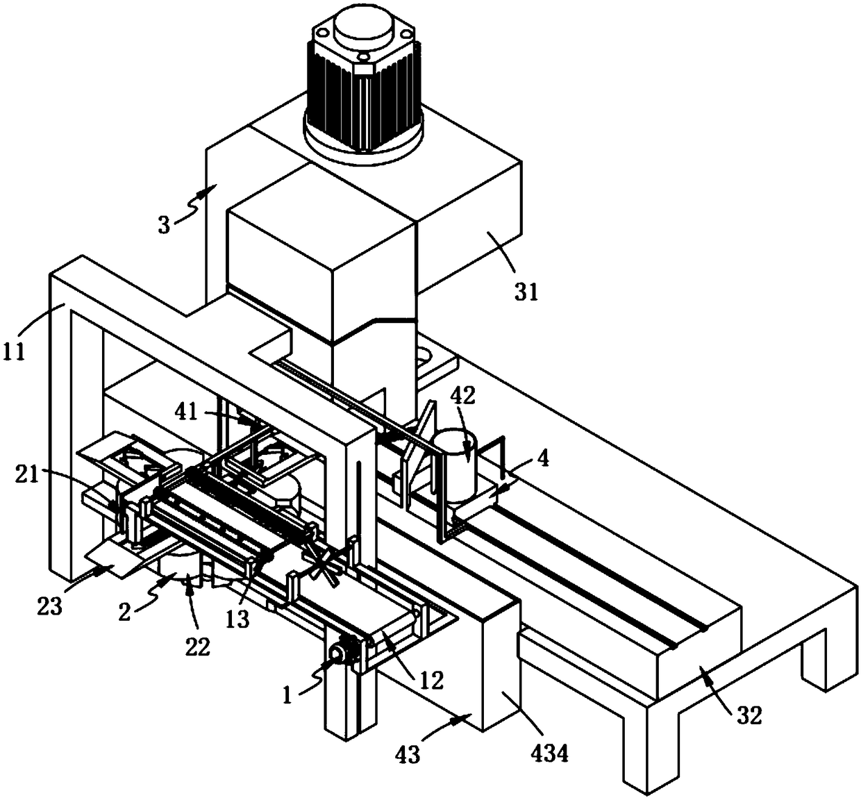
[0073] Such as figure 1 As shown, a fully automatic high-efficiency assembly equipment for inductance includes:

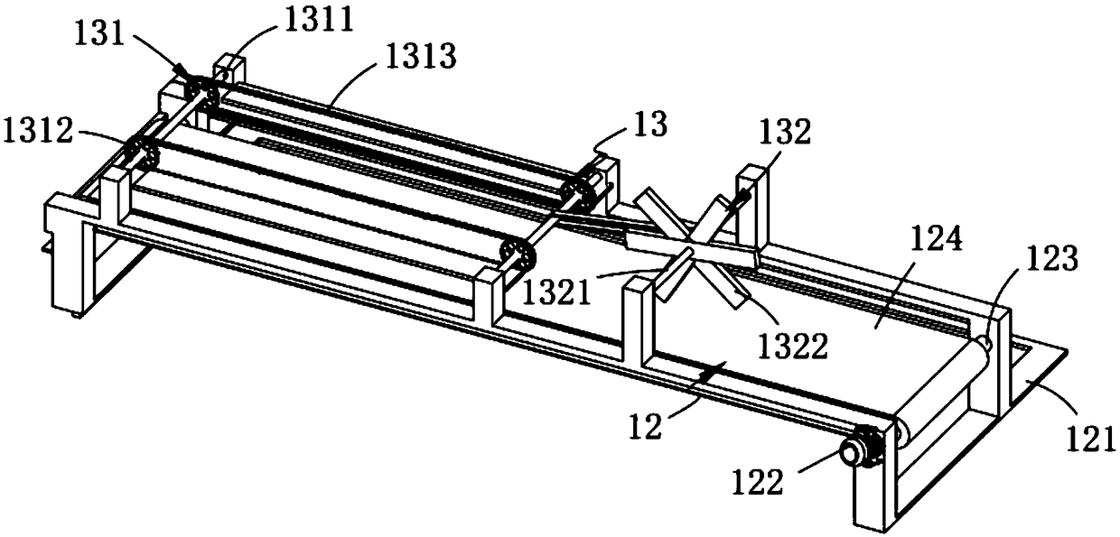
[0074] A wire flattening mechanism 1, the wire flattening mechanism 1 includes a frame 11, a conveying assembly 12 arranged on the frame 11, and a stretching assembly installed on the conveying assembly 12 and located above the conveying assembly 12 13;

[0075] The wire transmission mechanism 2, the wire transmission mechanism 2 includes a wire crimping assembly 21 arranged below the output end of the delivery assembly 12, a switching assembly 22 located below the crimping assembly 21 and rotatably arranged on the frame 11 and several clamping assemblies 23 arranged on the switching assembly 22 and arranged along the circumference of the switching assembly 22;

[0076] A wiring mechanism 3, the wiring mechanism 3 comprising a crimping machine 31 and a support assembly 32 fixedly connected to the crimping machine 31; and

[0077] The coil transmission mechanism ...

Embodiment 2

[0131] Such as Figure 8 , Figure 9 As shown, the components that are the same as or corresponding to those in the first embodiment are marked with the corresponding reference numerals in the first embodiment. For the sake of simplicity, only the differences from the first embodiment will be described below. The difference between this embodiment two and embodiment one is:

[0132] further, such as Figure 8 , Figure 9 As shown, the drive assembly 41 includes:

[0133] Flat push piece 411, described flat push piece 411 comprises the cylinder 4111 that is fixedly installed on the frame 11 by cylinder frame, the fixed rod 4112 that one end is fixedly connected with the telescoping end of described cylinder 4111 and the fixed rod 4112 that is connected with described fixed rod 4112 The other end is fixedly connected to the positioning tube 4113; and

[0134] The orientation member 412, the orientation member 412 includes a pull rod 4121 fixedly connected to the fixed rod 4...


PUM


Abstract

The invention relates to an inductor full-automatic and high-efficiency assembly device, comprising: a wire flattening mechanism, comprising a frame, a conveying assembly arranged on the frame and anextension assembly mounted on the conveying assembly and positioned above the conveying assembly; a wire transfer mechanism including a wire crimping assembly disposed below an output end of the transfer assembly, a switching assembly positioned below the wire crimping assembly and rotatably disposed on a rack, and a plurality of holding assemblies disposed on the switching assembly and disposed along a circumference of the switching assembly; a wiring mechanism including a wire pressing machine and a support assembly fixedly connected with the wire pressing machine; and a coil conveying mechanism comprising a drive assembly mounted on a rack, an upper coil assembly having one end connected to the drive assembly and the other end slidably mounted on the support assembly, and a discharge assembly disposed at an output end of the support assembly, wherein the upper coil assembly is connected to the drive assembly and the other end is slidably mounted on the support assembly. The invention solves the technical problem that the conductor is bent and twisted when the wiring is connected, and the conductor is manually straightened in the back sequence.

Description

technical field [0001] The invention relates to the technical field of inductance coil materials, in particular to a fully automatic and high-efficiency assembly equipment for inductance. Background technique [0002] The inductance coil is a device that uses the principle of electromagnetic induction to work. When a current flows through a wire, a certain electromagnetic field will be generated around the wire, and the wire itself of this electromagnetic field will be in the range of this electromagnetic field. The wires in the coil are induced, and the inductance coil is widely used. However, the existing inductance coils are troublesome to connect when assembling, and the installation is not firm, which affects the normal use of the inductance coils and cannot meet people's use needs. [0003] The patent document with the patent number CN207558571U discloses an inductance coil winding structure, including an inductance coil connection plate, an inductance coil connection ...

Claims


Application Information

Patent Timeline
Patent Type & Authority Applications(China)
IPC IPC(8): H01F41/00H01F41/10
CPCH01F41/00H01F41/10
Inventor 沈国栋
Owner 阜阳汇中芯自动化技术有限公司
Why Eureka
Try Eureka