
A vehicle-mounted 77GHz millimeter wave radar antenna

A millimeter-wave radar and antenna technology, which is applied to antennas, antenna arrays, antenna parts, etc., can solve the problems of high development cost of vehicle-mounted 77GHz millimeter-wave radar, the inability to popularize and apply middle and low-end vehicles, and the lack of mature technology of domestic manufacturers. The effect of large gain, narrow beam, and low sidelobe level

Inactive Publication Date: 2019-01-11
HUIZHOU DESAY SV AUTOMOTIVE
View PDF5 Cites 10 Cited by
  • Summary
  • Abstract
  • Description
  • Claims
  • Application Information

AI Technical Summary

Problems solved by technology

However, the current 77GHz millimeter-wave vehicle radar products are all foreign manufacturers, and domestic manufacturers have no mature technology
[0003] Due to the high development cost and high price of vehicle-mounted 77GHz millimeter-wave radar, it is mainly used in mid-to-high-end cars and cannot be widely applied to mid-to-low-end cars. Therefore, how to reduce costs and make a compromise between performance and price is particularly important.
Since the vehicle-mounted millimeter-wave radar is mainly installed in the front of the vehicle or in the front bumper, there are strict restrictions on the size of the radar. Currently, radar products on the market are limited by the size of the antenna and are generally too large.

Method used


Image

  • A vehicle-mounted 77GHz millimeter wave radar antenna
  • A vehicle-mounted 77GHz millimeter wave radar antenna
  • A vehicle-mounted 77GHz millimeter wave radar antenna

Examples


Embodiment 1

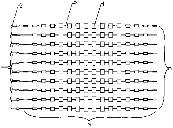
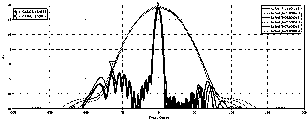
[0024] refer to figure 1 and 2 , a vehicle-mounted 77GHz millimeter-wave radar antenna, including m×n radiators 1, wherein m and n are both natural numbers greater than 3. Specifically, the specific number of radiators 1 can be selected according to parameters such as the radiation power of the radar antenna. This article The embodiment is described by taking m=16 and n=10 as an example, that is, a 16×10 planar array antenna structure. 16×10 radiators 1 form a planar array structure in the same plane, wherein, every 16 radiators 1 are connected in series to form a line array structure, and 10 line array structures are connected in parallel to form a planar array structure; each line The size of the radiator 1 in the array structure gradually decreases from the middle to the two sides. The area array antennas arranged in the same plane are adopted, and the size of the radiator 1 in each line array structure gradually decreases from the middle to both sides, so that the radar ...

Embodiment 2

[0031] refer to Figure 5 , the main structure of this embodiment is the same as that of Embodiment 1, the difference is that the radar antenna is formed by etching on the same PCB, and the copper foil on one side of the PCB is formed according to the shape of the radiator 1, the feeder 2, the power divider 3 and the matching network The copper foil on one side of the PCB is etched according to the set shape of the radiation part of the radiator 1, and the copper foil on the other side of the PCB is used as a ground wire as a whole.

[0032] The area array antenna, feeder, matching network and power divider are located in the same plane to make the connection between the antenna and the transmitting port of the RF chip smoother, and the final antenna debugging test is more convenient. Less loss, higher processing consistency and higher yield.


PUM


Abstract

The invention discloses a vehicle-mounted 77GHz millimeter wave radar antenna which belongs to the antenna technical field and solves the technical problem of optimizing sidelobe design. The main technical points are as follows: comprising m * n radiators (1), wherein m * n radiators (1) form a planar array structure in the same plane, and each m radiators (1) form a linear array structure in series, and n linear array structures are combined to form a planar array structure; the size of the radiator (1) in each of the linear array structures gradually decreases from the middle to both sides;Where m and n are all natural numbers greater than 3. The invention is used for a vehicle antenna.

Description

technical field [0001] The invention relates to the technical field of vehicle antennas, in particular to a vehicle 77GHz millimeter wave radar antenna. Background technique [0002] With the development of the economy, the number of private cars has increased sharply, and road traffic problems have become increasingly serious. As an effective means of preventing road traffic accidents, vehicle-mounted millimeter-wave radars have attracted more and more attention from major automobile manufacturers. In the millimeter wave frequency band, 77GHz millimeter wave radar has become the mainstream application and has broad development prospects. However, the current 77GHz millimeter-wave automotive radar products are all foreign manufacturers, and domestic manufacturers have no mature technology. [0003] Due to the high development cost and high price of vehicle-mounted 77GHz millimeter-wave radar, it is mainly used in mid-to-high-end cars and cannot be widely applied to mid-to-l...

Claims


Application Information

Patent Timeline
Patent Type & Authority Applications(China)
IPC IPC(8): H01Q21/00H01Q1/50H01Q1/38H01Q1/32
CPCH01Q1/3233H01Q1/38H01Q1/50H01Q21/00H01Q21/0075
Inventor 孙靖虎闻家毅
Owner HUIZHOU DESAY SV AUTOMOTIVE
Learn More