Laminator

A lamination machine and silicon steel lamination technology, which is applied in the field of motor rotor silicon steel lamination devices, can solve the problems affecting the uniformity of product quality, unqualified motor rotors, and low efficiency.

Active Publication Date: 2019-01-11
宁波傲天阔自动化设备有限公司
View PDF8 Cites 4 Cited by
  • Summary
  • Abstract
  • Description
  • Claims
  • Application Information

AI Technical Summary

Problems solved by technology

[0002] The motor rotor made of laminated silicon steel sheets needs to be glued on the upper and lower sides of the silicon steel sheet during heavy production. The traditional operation method is to manually apply glue to one side of the silicon steel sheet with a brush or glue spray gun. After the glue is glued, glue is applied to the other side. After both sides are coated with glue, the silicon steel sheet is put into the oven for drying. The glue covering both sides of the silicon steel sheet will flow downward under the action of gravity, resulting in uneven glue coating on the upper and lower sides of the silicon steel sheet, which will lead to unqualified motor rotors when the silicon steel sheet is laminated subsequently; Silicon steel sheets need to be stacked, and the upper and lower sheets will rotate at a certain angle when stacking. The traditional operation method is manual receiving operation. Affect the uniformity of product quality

Method used


Image

  • Laminator
  • Laminator
  • Laminator

Examples


Embodiment Construction

[0040] The following description serves to disclose the present invention to enable those skilled in the art to carry out the present invention. The preferred embodiments described below are only examples, and those skilled in the art can devise other obvious variations.

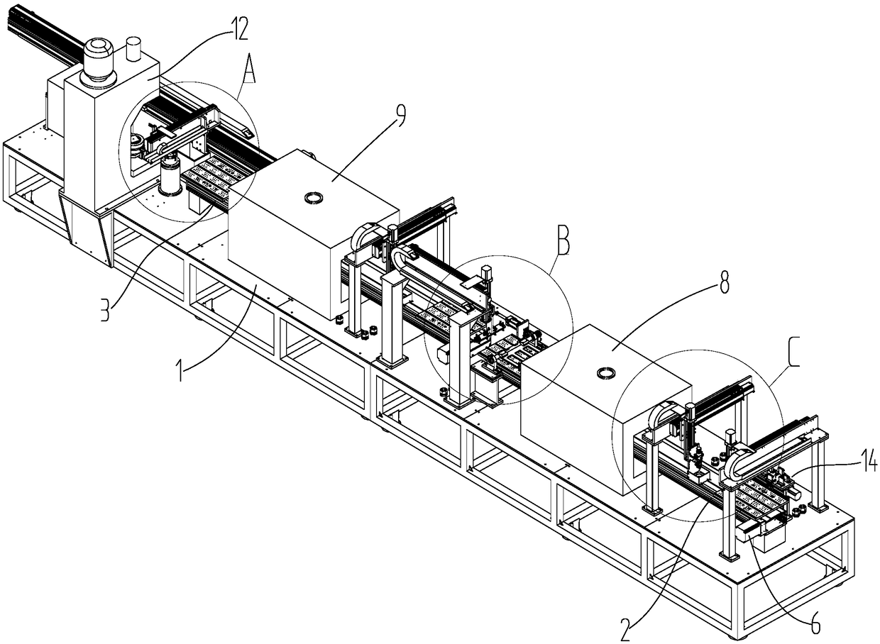
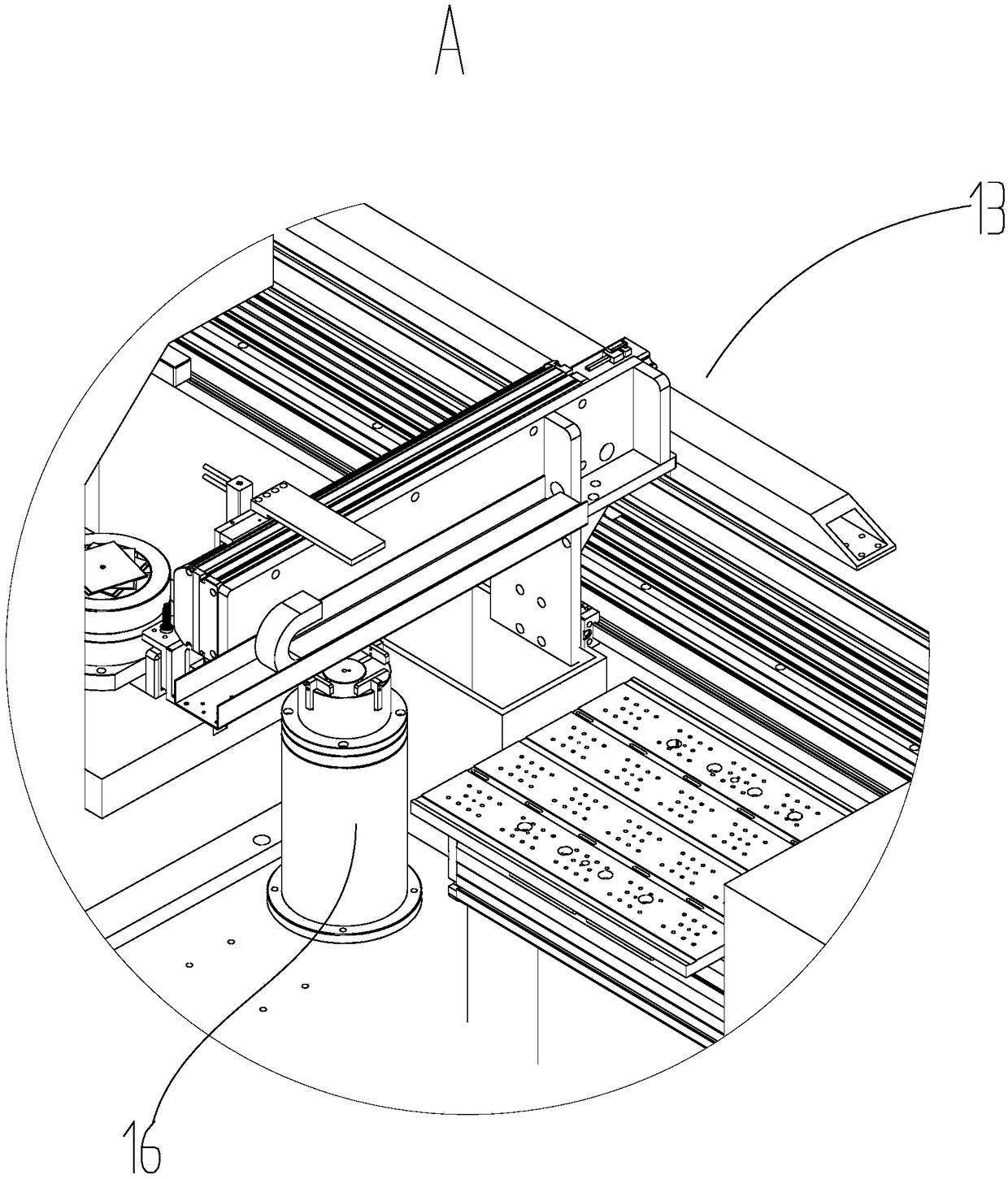
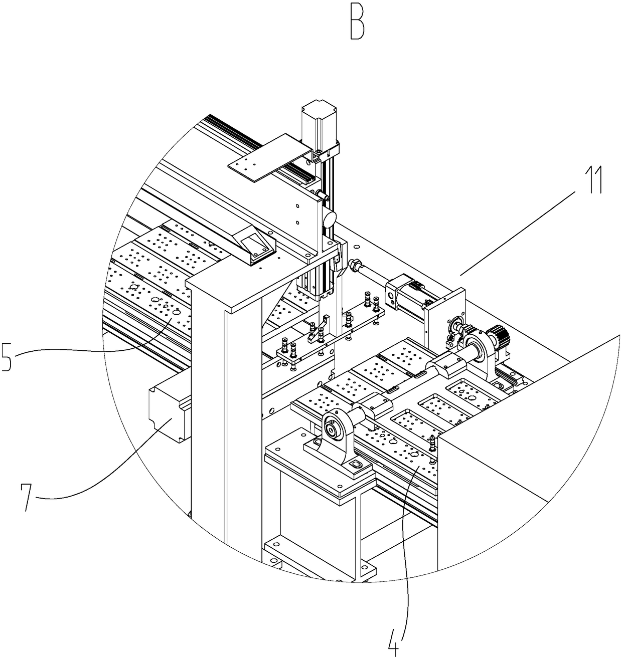
[0041] Such as Figure 1-5 Shown, a kind of stacking machine comprises a base 1, and a first transmission frame 2 arranged on the base, a second transmission frame 3 is installed on the right end of the first transmission frame 2 on the base 1, so The first transfer frame 2 and the second transfer frame 3 are respectively slidably connected with a first placement plate 4 and a second placement plate 5 for placing the silicon steel sheet 001, and the left end of the first transfer frame 2 is installed with a Place the first motor 6 of the plate 4 movement, the left end of the second transmission frame 3 is equipped with a second motor 7 for driving the movement of the second placement plate 5; the base 1 is ...


PUM


Abstract

The invention discloses a laminator laminator including a base, and a first conveyor rack disposed on the base, The base is provided with a second conveying frame mounted on the right end of the firstconveying frame, the first conveying frame and the second conveying frame are slidably connected with a first placing plate and a second placing plate, the left end of the first conveying frame is provided with a first motor, and the left end of the second conveying frame is provided with a second motor. A first drying box is erected on the base on the first conveyor frame, and a second drying box is erected on the second conveyor frame. The left side of the first drying oven and the second drying oven is provided with a silicon steel sheet gluing device on the base; a silicon steel sheet turnover device is mounted on the base at the right end of the first conveying frame. A prepressing device and a silicon steel sheet clamping device are installed on the right end of the second conveyingframe on the base; the laminator is not only easy to operate, but also can greatly improve the laminating efficiency, reduce the manpower input, and ensure the quality of coating and laminating silicon steel sheet.

Description

technical field [0001] The invention relates to the technical field of a lamination device for silicon steel sheets of a motor rotor, in particular to a lamination machine. Background technique [0002] The motor rotor made of laminated silicon steel sheets needs to be glued on the upper and lower sides of the silicon steel sheet during heavy production. The traditional operation method is to manually apply glue to one side of the silicon steel sheet with a brush or glue spray gun. After the glue is glued, glue is applied to the other side. After both sides are coated with glue, the silicon steel sheet is put into the oven for drying. The glue covering both sides of the silicon steel sheet will flow downward under the action of gravity, resulting in uneven glue coating on the upper and lower sides of the silicon steel sheet, which will lead to unqualified motor rotors when the silicon steel sheet is laminated subsequently; Silicon steel sheets need to be stacked, and the up...

Claims


Application Information

Patent Timeline
Patent Type & Authority Applications(China)
IPC IPC(8): H02K15/02H02K15/12
CPCH02K15/02H02K15/12
Inventor 李波黎赟胡炜
Owner 宁波傲天阔自动化设备有限公司
Why Eureka
Try Eureka