Camera module and fixing device of camera module

A camera module and fixing device technology, applied in the field of photography, can solve problems such as difficult to stabilize, easy to loose the fixed position, heavy weight of the lens module, etc., to achieve the effect of not easy to fix, not easy to loose, and reliable connection

Inactive Publication Date: 2019-01-11
TRULY OPTO ELECTRONICS
View PDF0 Cites 6 Cited by
  • Summary
  • Abstract
  • Description
  • Claims
  • Application Information

AI Technical Summary

Problems solved by technology

For large-size lenses in vehicle-mounted electronic equipment or other precision equipment (compared to cameras in the communications industry such as mobile phone products), the lens is generally connected to the lens base, and the bottom plate of the lens base is fixedly connected to an external fixture by gluing or screws. ,like figure 1 As shown, due to the long length of the lens 2, the heavy weight of the lens module, and the horizontal setting of the lens 1, only relying on the fixing method of the bottom plate 13 of the lens base 1, the fixed position is prone to loosening and it is difficult to stabilize, so a more stable fixing method is required. Way

Method used


Image

  • Camera module and fixing device of camera module
  • Camera module and fixing device of camera module
  • Camera module and fixing device of camera module

Examples


Embodiment 1

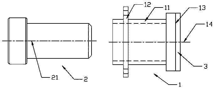
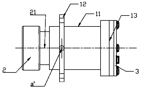
[0035] Such as Figure 2~Figure 3 As shown, a camera module provided by an embodiment of the present invention includes a lens 2 and a lens base 1; the lens 2 has a first axis 21, and the first axis 21 is arranged laterally. The landscape setting can be as figure 2 The setting shown in is parallel to the horizontal line; or in other embodiments, the setting is roughly parallel to the horizontal line, for example, the angle with the horizontal line is within the range of plus 20 degrees and minus 20 degrees.

[0036] The camera module in this embodiment is more specifically a large-size camera module, and the large size is relative to a camera in the communication industry such as a mobile phone product. The length of the lens 2 of the camera module is not less than 20mm, or the weight of the lens 2 is not less than 15G.

[0037] The lens base 1 includes a lens accommodation part 11 and a fixed connection part 12 for fixed connection with the outside; the lens accommodation ...

Embodiment 2

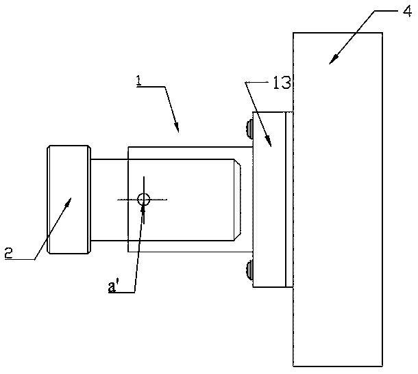
[0052] The present invention also provides a camera module fixing device 4, the camera module is the camera module in the first embodiment above, and the fixing device 4 has a through hole 41 matched with the lens accommodating part 11; After a part of the camera module passes through the through hole 41 , the lens base 1 of the camera module is fixed on the fixing device 4 through the fixed connection part 12 .

[0053] When the fixed connection part 12 is the second solution in the first embodiment, after the hollow shell 11 of the lens base 1 passes through the through hole 41 of the fixing device 4, it is attached to the corresponding surface of the fixing device through the ring structure 121 Make a permanent connection.

[0054] When the fixed connection part 12 is the third scheme or the fourth scheme in the first embodiment, as Figure 5~Figure 7 As shown, the fixing device 4 also has a space 42 matching the fixed connection portion 12 of the lens base 1 and a rotatio...


PUM


Abstract

The present invention provides a camera module. The camera module comprises a lens and a lens substrate; the lens has a first shaft which is transversely arranged; the lens substrate comprises a lensholding portion and a fixing connection portion fixedly connected with the external portion; the lens holding portion is a hollow cavity, and the fixing connection portion is protruded on the outer peripheral surface of the hollow cavity; and the gravity position of the camera module is located in a geometric space limited by the fixing connection portion. The present invention further provides afixing device of the camera module. The fixing device has a through hole matched with the lens holding portion; and one part of the camera module passes through the through hole and then is fixed on the fixing device through the fixing connection portion. The embodiment of the invention provides a large-scale camera module. Through ingenious design of the fixing connection portion on the lens substrate, when the large-scale camera module is fixedly connected with the external portion, the connection is firm and is not easy to be loosened, and the problem is solved that the large-scale lens isnot easily fixed.

Description

technical field [0001] The invention relates to the field of camera technology, in particular to a camera module and a fixing device for the camera module. Background technique [0002] In the communication industry, such as mobile phone products, the traditional lens weight is relatively small and the length is short. The fixing method of this lens is to directly glue the base to the circuit board at the bottom. For large-size lenses in vehicle-mounted electronic equipment or other precision equipment (compared to cameras in the communications industry such as mobile phone products), the lens is generally connected to the lens base, and the bottom plate of the lens base is fixedly connected to an external fixture by gluing or screws. ,Such as figure 1 As shown, due to the long length of the lens 2, the heavy weight of the lens module, and the horizontal setting of the lens 1, only relying on the fixing method of the bottom plate 13 of the lens base 1, the fixed position is...

Claims


Application Information

Patent Timeline
Patent Type & Authority Applications(China)
IPC IPC(8): H04N5/225
CPCH04N23/51H04N23/50H04N23/55
Inventor 王军
Owner TRULY OPTO ELECTRONICS
Why Eureka
Try Eureka