An Interpolar Cryoablation Catheter

An ablation catheter and inter-electrode technology, which is applied in the field of inter-electrode cryoablation catheter, can solve the problems of overheating of myocardial tissue, inability to ablate ablation electrodes, scab formation, etc., and achieve the effect of improving safety

Active Publication Date: 2020-11-17
SICHUAN JINJIANG ELECTRONICS SCI & TECH CO LTD
View PDF11 Cites 0 Cited by
  • Summary
  • Abstract
  • Description
  • Claims
  • Application Information

AI Technical Summary

Problems solved by technology

[0005] In this way, electrodes widely used at present are electrodes with a spherical shape and cylindrical electrodes with spherical ends, which have a small diameter and exhibit excellent operability. However, these electrodes have the following disadvantages: the output power is small, the electrode Inability to achieve adequate contact with or fixation to the organism, minimal cooling with circulating blood, and ablation limited to a small area around the area pushed into by the tip electrode
In order to achieve a deeper ablation depth, higher ablation energy will be used clinically, which will often cause local overheating of myocardial tissue and cause scab, thus affecting the effectiveness and safety of the operation. The saline cools down the ablation part, and a series of complications will occur due to the continuous delivery of saline to the patient during the operation
[0006] At the same time, the current conventional ablation electrodes cannot directly perform ablation after stimulation and mapping to the target position without moving the ablation electrode position, or an additional mapping catheter is required for mapping stimulation during ablation.

Method used


Image

  • An Interpolar Cryoablation Catheter
  • An Interpolar Cryoablation Catheter
  • An Interpolar Cryoablation Catheter

Examples


Embodiment 1

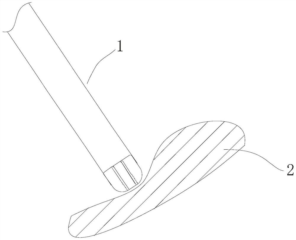
[0035] Such as Figure 1-4 , an interpolar cryoablation catheter 1, comprising:

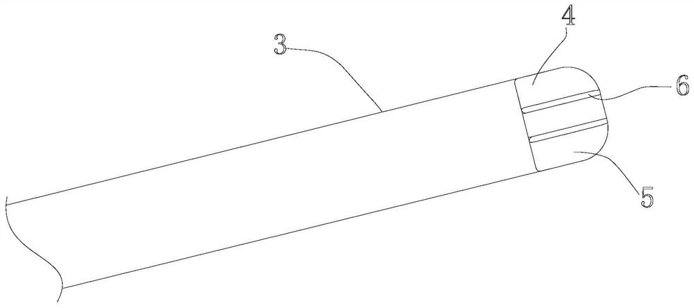
[0036] a flexible insertion tube 3 having a distal end for insertion into a patient's body cavity;

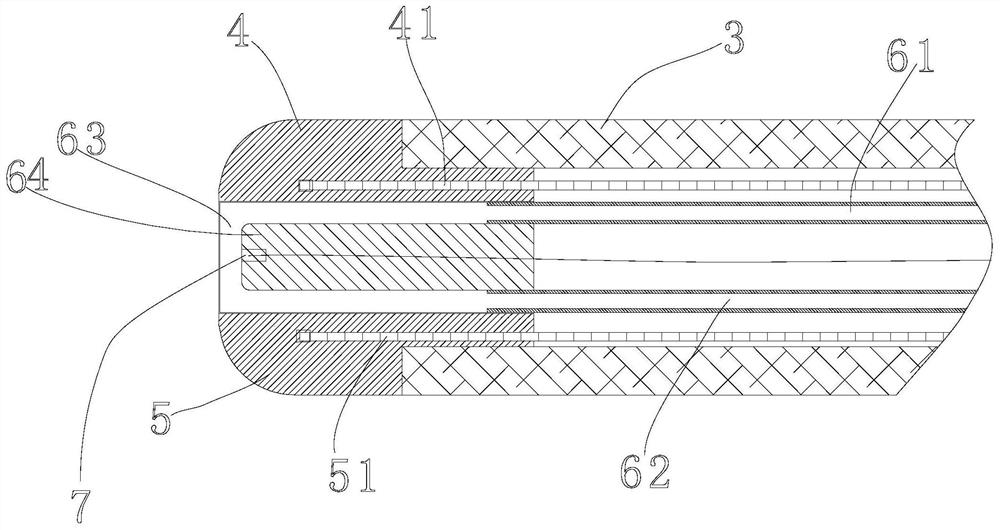
[0037] Electrodes, the number of electrodes is more than two (two in this embodiment, respectively electrode A4 and electrode B5, the electrode A4 and electrode B5 are two symmetrically arranged electrodes, and the outer surface of the electrode is an arc surface ), are installed at the distal end in a mutually spaced and insulated manner, the electrodes have an outer surface for contacting the patient's heart tissue 2, and more than two electrodes are configured to cooperate with each other to map or electrically map the heart tissue 2 Stimulate;

[0038] A circulating freezing cavity, the circulating freezing cavity is arranged in the flexible insertion tube 3 and extends from the distal end of the flexible insertion tube 3 into the gap between the electrodes, and the cavity in the gap is sepa...

Embodiment 2

[0045] Compared with Embodiment 1, this embodiment differs in that the contact part 6 is made of polyurethane, and the freezing medium 8 is liquid carbon dioxide.

Embodiment 3

[0047] Compared with Embodiment 1, this embodiment differs in that the contact part 6 is made of platinum-iridium alloy, and the freezing medium 8 is liquid hydrofluorocarbon (HFC).


PUM


Abstract

The invention relates to the field of cryoablation, in particular to an interpolar cryoablation catheter, comprising a flexible insertion tube having a distal end for insertion into a body cavity of apatient; more than two electrodes spaced apart and insulated with each other at the distal end, with the electrodes having an outer surface for contacting cardiac tissue of a patient, and two or moreelectrodes being configured to map or electrically stimulate cardiac tissue in cooperation with each other; a circulating freezing chamber disposed within the flexible insertion tube and extending from the distal end of the flexible insertion tube into a spacing of the electrodes, with the spaced cavities being spaced from the heart tissue and the cavities containing the circulating freezing medium. The invention aims at providing an inter-polar cryoablation catheter with mapping and stimulation functions, and reducing operation difficulty, pain of the patient and cost under the condition ofensuring cardiac tissue ablation effect, improving safety and reducing possibility of complications of the patient.

Description

technical field [0001] The invention relates to the field of cryoablation, in particular to an interpolar cryoablation catheter. Background technique [0002] Arrhythmia is one of the common heart diseases in the world. There are many types of arrhythmias, including arrhythmias in the atrium, such as atrial premature contraction, atrial flutter, bypass tachycardia, atrial fibrillation, and AV node Reentrant tachycardia, intraventricular ventricular arrhythmias such as premature ventricular contractions, ventricular tachycardia, ventricular fibrillation, and long-term QT ​​syndrome, and disorders involving slow heart rhythms that can originate in the conduction system of the heart Chronic arrhythmia, radiofrequency ablation catheters or cryoablation catheters have been widely used clinically to treat such diseases. [0003] Before ablation, it is necessary to accurately locate the lesion site. The current commonly used technique is to place an additional mapping catheter bef...

Claims


Application Information

Patent Timeline
Patent Type & Authority Patents(China)
IPC IPC(8): A61B18/02
CPCA61B18/02A61B2018/00023A61B2018/00095A61B2018/00577A61B2018/00642A61B2018/00839A61B2018/00904A61B2018/0262A61B2018/0293
Inventor 朱晓林邹波李楚武
Owner SICHUAN JINJIANG ELECTRONICS SCI & TECH CO LTD
Why Eureka
Try Eureka