A high-efficiency soot blowing device for scr denitrification catalyst

A denitration catalyst and soot blowing device technology, applied in chemical instruments and methods, separation methods, dispersed particle separation, etc., can solve problems such as unhealthy health, fugitive dust, polluted air, etc., and achieve loosening and falling rate improvement and removal effect. Improvement, soot blowing effect improvement effect

Active Publication Date: 2020-05-05
HEBEI HANTANG HONGYUAN ENVIRONMENT PROTECTION TECH
View PDF6 Cites 0 Cited by
  • Summary
  • Abstract
  • Description
  • Claims
  • Application Information

AI Technical Summary

Problems solved by technology

There will be dust in the dust cleaning process. If it is not airtight and manual dust removal is used, dust inhalation will be harmful to human health and pollute the air. Therefore, it is necessary to develop a closed automatic soot blowing device to protect human health and the atmospheric environment.

Method used


Image

  • A high-efficiency soot blowing device for scr denitrification catalyst
  • A high-efficiency soot blowing device for scr denitrification catalyst
  • A high-efficiency soot blowing device for scr denitrification catalyst

Examples


Embodiment Construction

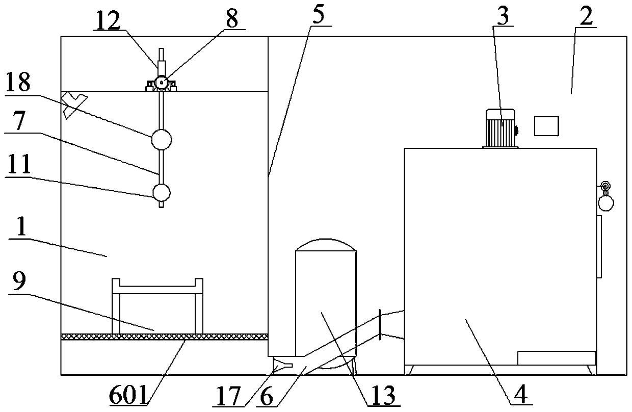
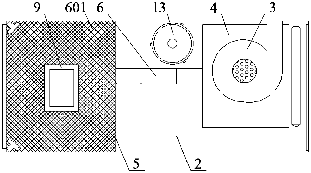
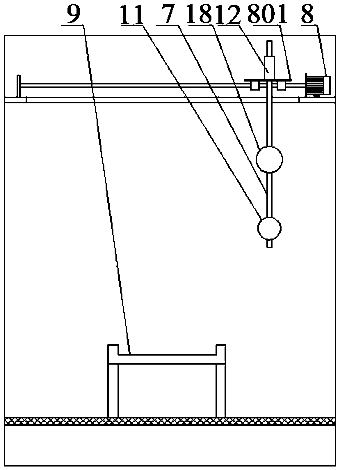
[0023] The invention relates to a high-efficiency soot blowing device for SCR denitration catalyst. The device includes a purge unit connected to an air compressor, a catalyst placement platform 9 and a negative pressure unit. The soot blowing device includes a partition 5 Separate the purge room 1 and the dust removal room 2, the placement platform 9 is located in the purge room 1, the purge unit is set on the top of the purge room 1, the negative pressure unit includes the air inlet upward and located below the placement platform 9 The suction channel 6 is provided with a mesh plate 601 at the air inlet. The suction channel 6 passes through the partition 5 and is connected to the negative pressure unit; the blowing unit includes a blowing unit fixed on the top of the blowing chamber 1 by means of a horizontal moving mechanism. Sweep tube 7, the end of the purge tube 7 is provided with a circular cavity 11, the circular cavity 11 is provided with a rotating frame 14, and the ci...


PUM

PropertyMeasurementUnit
thicknessaaaaaaaaaa

Abstract

The invention relates to a high-efficiency soot blowing device for an SCR (selective catalytic reduction) denitration catalyst. The high-efficiency soot blowing device for the SCR denitration catalystcomprises a purging chamber and a dust removing chamber which are separated by a partition plate, wherein a placing platform is positioned in the purging chamber, and a purging unit is arranged at the top of the purging chamber; a negative pressure unit comprises an air suction channel which is provided with an upward air inlet and positioned below the placing platform, and a screen plate is arranged at the air inlet; the air suction channel penetrates through the partition plate and is connected with the negative pressure unit, and the purging unit comprises a purging pipe which is fixedly arranged at the top of the purging chamber by a horizontal moving mechanism; the tail end of the purging pipe is provided with a circular cavity, and a turret is arranged in the circular cavity; sealing rolling balls which are matched with an air outlet of the circular cavity are uniformly distributed on the circumference of the turret, and the sealing rolling balls are arranged on the turret by anelastic bracket; a funnel tube is arranged in the air suction channel, and the funnel tube forms an opening and closing unit of the air suction channel by the air pressure change of the purging chamber. The device adopts the combination of various forms of pressure multi-change, positive and negative pressure change, and sudden change to remove dust from the catalyst, and the soot blowing effectis significantly improved.

Description

Technical field [0001] The invention belongs to the technical field of catalyst cleaning and recovery, and in particular relates to a high-efficiency soot blowing device for an SCR denitration catalyst. Background technique [0002] SCR denitration process is currently the most effective method for coal-fired boilers to achieve flue gas denitration, and it is also a widely used process. The denitration catalyst, a key component of the process, will be deactivated after 24,000 hours of operation, the denitration efficiency of the unit will decrease, the ammonia escape rate will increase, and the flue gas will not meet the emission standards. Based on the principle of resource reuse and cost saving, thermal power plants often choose to regenerate catalysts that are mechanically intact to restore their activity. One of the main reasons for the deactivation of the denitration catalyst is the clogging of fly ash, so ash removal becomes the first step in the regeneration of the denitr...

Claims


Application Information

Patent Timeline
Patent Type & Authority Patents(China)
IPC IPC(8): B01D53/96B01D53/88B01D53/56B01D46/02
CPCB01D46/02B01D53/8625B01D53/88B01D53/90B01D53/96
Inventor 孙红娟薛勇江任世儒徐建林曹军平赵贵民
Owner HEBEI HANTANG HONGYUAN ENVIRONMENT PROTECTION TECH
Why Eureka
Try Eureka