An efficient reaction kettle with an improved heat dissipation speed

A technology of heat dissipation speed and reactor, which is applied in chemical/physical/physical chemical fixed reactors, chemical/physical/physical chemical processes, chemical instruments and methods, etc., can solve the problem of high cost and achieve low cost and good effect , the effect of compact structure design

Active Publication Date: 2019-01-15
滨州海川生物科技股份有限公司
View PDF5 Cites 5 Cited by
  • Summary
  • Abstract
  • Description
  • Claims
  • Application Information

AI Technical Summary

Problems solved by technology

When mixing, a large amount of heat is prone to occur, and the temperature is generally cooled by supplying water. For example, the Chinese invention patent with the patent number CN201610393795.6 discloses a new type of reaction kettle with automatic temperature control function, including the kettle body, the The power mechanism above the kettle body, the stirring mechanism and the temperature sensor are arranged inside the kettle body. The new type of reaction kettle with control function passes through the through hole on the slurry, so that the material forms a cross flow when being stirred, which improves the adequacy of stirring and the practicability of the reaction kettle; not only that, during the stirring process, through the temperature sensor The temperature in the kettle body is detected in real time, and then the driving component controls the air to continuously enter the shell, and the heat exchanger in the shell condenses the air, and then makes condensed water, and finally cools the kettle through the cooling tube around the kettle body. The temperature of the body is controlled, thereby improving the reliability of the reactor; in summary, the patent still uses a heat exchanger to condense the air, and uses condensed water to exchange heat to export the heat in the reactor, but in fact, this method is expensive. , not suitable for small and medium manufacturers

Method used


Image

  • An efficient reaction kettle with an improved heat dissipation speed
  • An efficient reaction kettle with an improved heat dissipation speed
  • An efficient reaction kettle with an improved heat dissipation speed

Examples


Embodiment 1

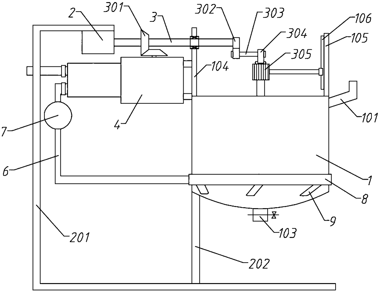
[0041] A high-efficiency reaction kettle for accelerating heat dissipation, including a tank body 1, a mounting frame 201, a lifting component and a suction structure 4;

[0042] The mounting frame 201 is a similar C-shaped plate bent up and down, and the upper end is bent shorter than the lower end; the tank body 1 is arranged on the left side of the mounting frame 201, and the left end of the bottom of the tank body 1 is fixedly connected to the lower end of the mounting frame 201 through a support rod 202; A driving motor 2 is installed on the upper end of the frame 201, and the output end of the driving motor 2 protrudes horizontally to the right and is connected with a driving shaft 3, and the driving shaft 3 is arranged higher than the tank body 1;

[0043] A liquid inlet pipe 101 is connected to the top of one side of the tank body 1; a vertical left support plate 104 and a right support plate 105 are fixedly connected to the left and right ends of the top of the tank bo...

Embodiment 2

[0054] A high-efficiency reaction kettle for accelerating heat dissipation, including a tank body 1, a mounting frame 201, a lifting component and a suction structure 4;

[0055] The mounting frame 201 is a similar C-shaped plate bent up and down, and the upper end is bent shorter than the lower end; the tank body 1 is arranged on the left side of the mounting frame 201, and the left end of the bottom of the tank body 1 is fixedly connected to the lower end of the mounting frame 201 through a support rod 202; A driving motor 2 is installed on the upper end of the frame 201, and the output end of the driving motor 2 protrudes horizontally to the right and is connected with a driving shaft 3, and the driving shaft 3 is arranged higher than the tank body 1;

[0056] A liquid inlet pipe 101 is connected to the top of one side of the tank body 1; a vertical left support plate 104 and a right support plate 105 are fixedly connected to the left and right ends of the top of the tank bo...

Embodiment 3

[0065] A high-efficiency reaction kettle for accelerating heat dissipation, including a tank body 1, a mounting frame 201, a lifting component and a suction structure 4;

[0066] The mounting frame 201 is a similar C-shaped plate bent up and down, and the upper end is bent shorter than the lower end; the tank body 1 is arranged on the left side of the mounting frame 201, and the left end of the bottom of the tank body 1 is fixedly connected to the lower end of the mounting frame 201 through a support rod 202; A driving motor 2 is installed on the upper end of the frame 201, and the output end of the driving motor 2 protrudes horizontally to the right and is connected with a driving shaft 3, and the driving shaft 3 is arranged higher than the tank body 1;

[0067] A liquid inlet pipe 101 is connected to the top of one side of the tank body 1; a vertical left support plate 104 and a right support plate 105 are fixedly connected to the left and right ends of the top of the tank bo...


PUM


Abstract

The invention relates to the technical field of reaction kettles and particularly relates to an efficient reaction kettle with an improved heat dissipation speed. Outside air is suctioned to directlycool the reaction kettle with a low cost and good effect. A drive motor drives a drive shaft to rotate. A pulling assembly drives a stirring motor, a rotation shaft and stirring rods to move up and down, thus changing the stirring zone. By starting the stirring motor and stirring a reaction solution with the stirring rods, uniformity is achieved and heat dissipation is accelerated. The drive motordrives a suction assembly to convey outside air to an air guide ring, and the air is fed to the bottom of a tank body through air guide pipes in a characteristic distribution to form eddy airflow, thus bringing heat and improving mixing. The pulling assembly and the suction assembly are driven by the same motor so that the structure is compact. An air conveying pipe is provided with a buffer chamber preventing reversed suction, thus effectively preventing the solution in the tank body to flow back into the suction assembly so as to avoid device damage.

Description

technical field [0001] The invention relates to the technical field of reactors, in particular to a high-efficiency reactor for accelerating heat dissipation. Background technique [0002] The relationship between human beings and chemical industry is very close, and it has spread to all aspects of life. In modern life, chemical products are inseparable almost anytime and anywhere. From material life such as clothing, food, housing and transportation to spiritual life such as culture, art and entertainment, chemical products are required to serve them. Some chemical products play an epoch-making important role in the history of human development. Their production and application even represent a certain historical stage of human civilization. [0003] The broad understanding of the reaction kettle is a stainless steel container with physical or chemical reactions. The structural design and parameter configuration of the container are carried out according to different proc...

Claims


Application Information

Patent Timeline
Patent Type & Authority Applications(China)
IPC IPC(8): B01J19/18
CPCB01J19/0053B01J19/0066B01J19/18
Inventor 方期洲
Owner 滨州海川生物科技股份有限公司
Why Eureka
Try Eureka