
Oil pollution clearing device for mechanical equipment

A technology of mechanical equipment and cleaning device, applied in lighting and heating equipment, dryer, drying gas arrangement, etc., can solve the problems of inconvenient adjustment of the distance between the bristles and the cleaning handpiece, affecting the use effect, and inconvenience in taking out sewage, etc.

Inactive Publication Date: 2019-01-15
谢森涛
View PDF6 Cites 6 Cited by
  • Summary
  • Abstract
  • Description
  • Claims
  • Application Information

AI Technical Summary

Problems solved by technology

However, the cleaning device of the above design is inconvenient to adjust the distance between the bristles and the cleaning muff, which limits the cleaning range of the bristles, and it is inconvenient to take out the sewage generated during the cleaning process, which affects the use effect. Therefore, we propose a mechanical equipment oil cleaning device to solve the above problems

Method used


Image

  • Oil pollution clearing device for mechanical equipment
  • Oil pollution clearing device for mechanical equipment
  • Oil pollution clearing device for mechanical equipment

Examples


Embodiment

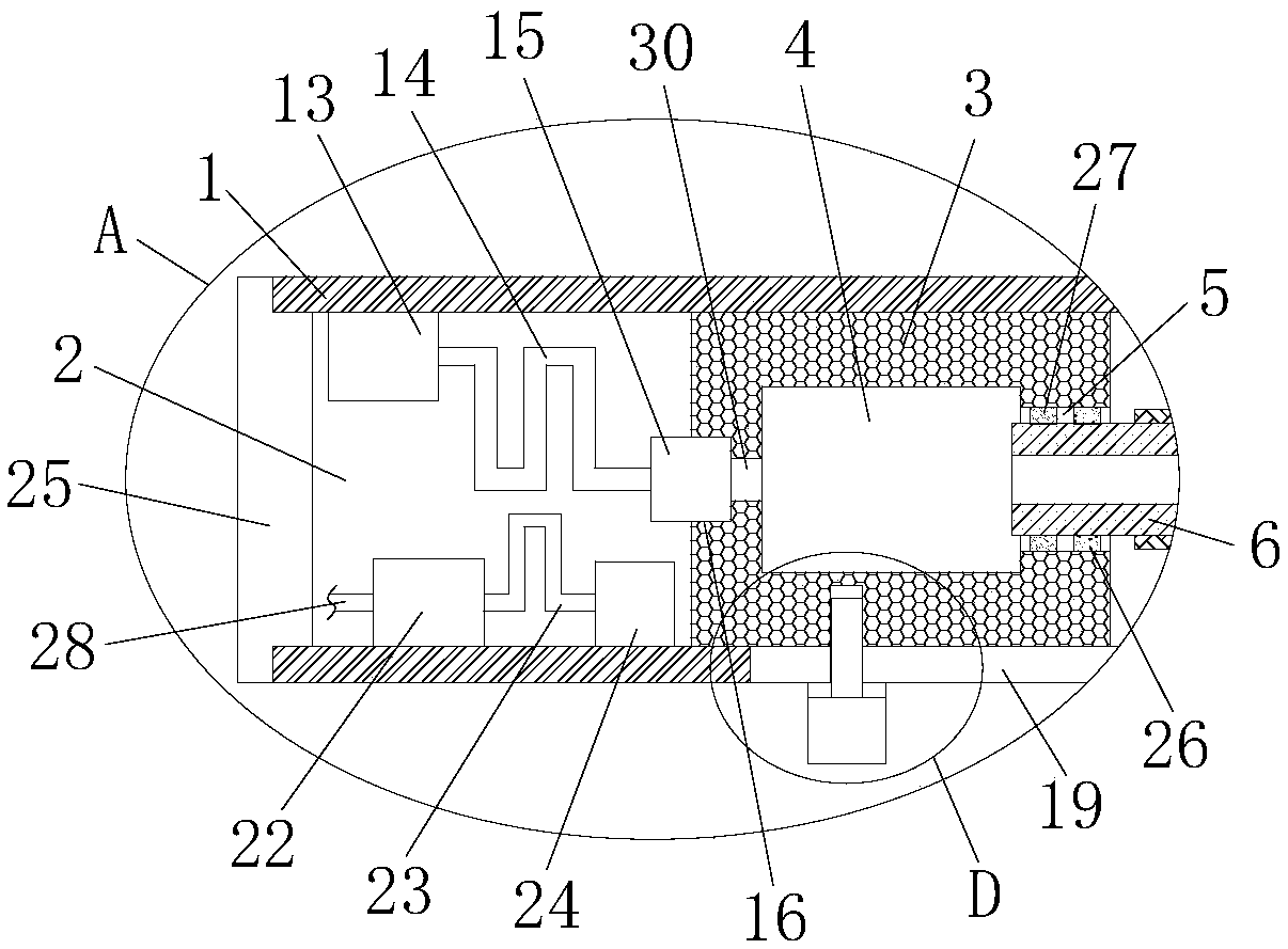
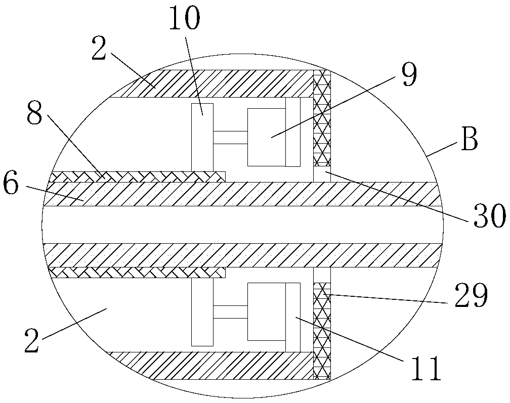
[0027] refer to Figure 1-5In this embodiment, a device for cleaning oil from mechanical equipment is proposed, which includes a handle 1, a through hole 2 is provided at one end of the handle 1, an air box 3 is slidably installed in the through hole 2, and a chamber 4 is provided on the air box 3. One side of the inner wall of the chamber 4 is provided with a rotating hole 5, and a sleeve 6 is rotated in the rotating hole 5, and one end of the sleeve 6 extends to the outside of the handle 1 and is set in a closed state, and the outside of the sleeve 6 is fixedly installed. There are a plurality of bristles 7, and the inner wall of the casing 6 is provided with a plurality of communication holes 12, and the top inner wall and the bottom inner wall of the through hole 2 are welded with a mounting rod 11, and a motor 9 is fixedly installed on one side of the mounting rod 11. A gear 10 is fixedly installed on the output shaft of 9, a rack 8 is arranged on the outside of the casin...


PUM


Abstract

The invention discloses an oil pollution clearing device for mechanical equipment. The oil pollution clearing device comprises a handle; a through hole is formed in one end of the handle; an air box is slidably mounted in the through hole; a cavity is formed in the air box; a rotating hole is formed in the inner wall of one side of the cavity; a sleeve is rotatably mounted in the rotating hole, and one end of the sleeve extends to the outer side of the handle and is arranged to be in a closed state; a plurality of brush bristles are fixedly mounted on the outer side of the sleeve; a pluralityof communicating holes are formed in the inner wall of the sleeve; mounting rods are welded to the inner walls of the top and the bottom of the through hole correspondingly; motors are mounted on onesides of the mounting rods, and gears are fixedly mounted on output shafts of the motors; and a rack is arranged on the outer side of the sleeve, and the two gears are engaged with the rack. The oil pollution clearing device is reasonable in design and high in practicability, the distance between the brush bristles and the handle is convenient to adjust, the to-be-washed part of the mechanical equipment can be dried, sewage at the to-be-washed part can be cleared, various clearing functions are achieved, and using is facilitated.

Description

technical field [0001] The invention relates to the technical field of cleaning equipment, in particular to a mechanical equipment oil pollution cleaning device. Background technique [0002] Machinery is a tool used by human beings to understand and transform the living environment. With the development of society, various mechanical equipment has penetrated into people's daily life and become an indispensable part of human society. During the use of mechanical equipment, there will be Mechanical wear requires lubricating oil to lubricate, which will inevitably cause lubricating oil to pollute the mechanical equipment, so cleaning the oil on the mechanical equipment is also a work that often needs to be done during the use of the mechanical equipment. [0003] After retrieval, the patent document with the application number 201710894878.8 discloses a mechanical equipment oil cleaning device, including a cleaning muff, a single-pole double-throw switch and a control switch a...

Claims


Application Information

Patent Timeline
IPC IPC(8): B08B1/04B08B3/02F26B21/00
CPCF26B21/004B08B3/02B08B1/12B08B1/32
Inventor 谢森涛
Owner 谢森涛
Learn More