
Wheel hub spinning machine

A spinning machine and wheel hub technology, applied in the field of wheel hub production equipment, can solve problems such as unloading, shaking, and bending of the rotating shaft, and achieve the effects of precise hydraulic cylinder stroke control, eliminating structural damage, and improving stability

Inactive Publication Date: 2019-01-15
ANHUI STRONG AUTO PARTS
View PDF9 Cites 8 Cited by
  • Summary
  • Abstract
  • Description
  • Claims
  • Application Information

AI Technical Summary

Problems solved by technology

[0004] Although this solution can realize the spinning forming of the wheel hub, it has the following disadvantages: On the one hand, it drives the wheel hub blank to rotate through the spinning machine, and the rotating shaft located above is driven. The rotational speed difference between the upper and lower sides when starting, the torque difference formed by the rotational speed difference will affect the structural strength of the formed hub in the form of torsion; on the other hand, the fence part used for spinning forming cannot bear a large force , cannot be applied to splitting, pushing and other processes, otherwise it will cause problems such as distortion, deformation, shaking, etc., and the scope of production is small; on the other hand, the upper template is rotated and supported by an isolated rotating shaft, combined The side part of the slab is unstable in its lateral force structure, and the change of torque during the spinning process is likely to cause bending of the spinning shaft and other problems that affect the quality of the molding.

Method used


Image

  • Wheel hub spinning machine
  • Wheel hub spinning machine
  • Wheel hub spinning machine

Examples


Embodiment Construction

[0028] The present invention is described in detail below in conjunction with accompanying drawing:

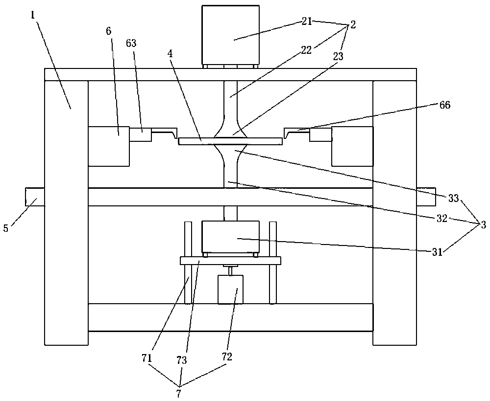
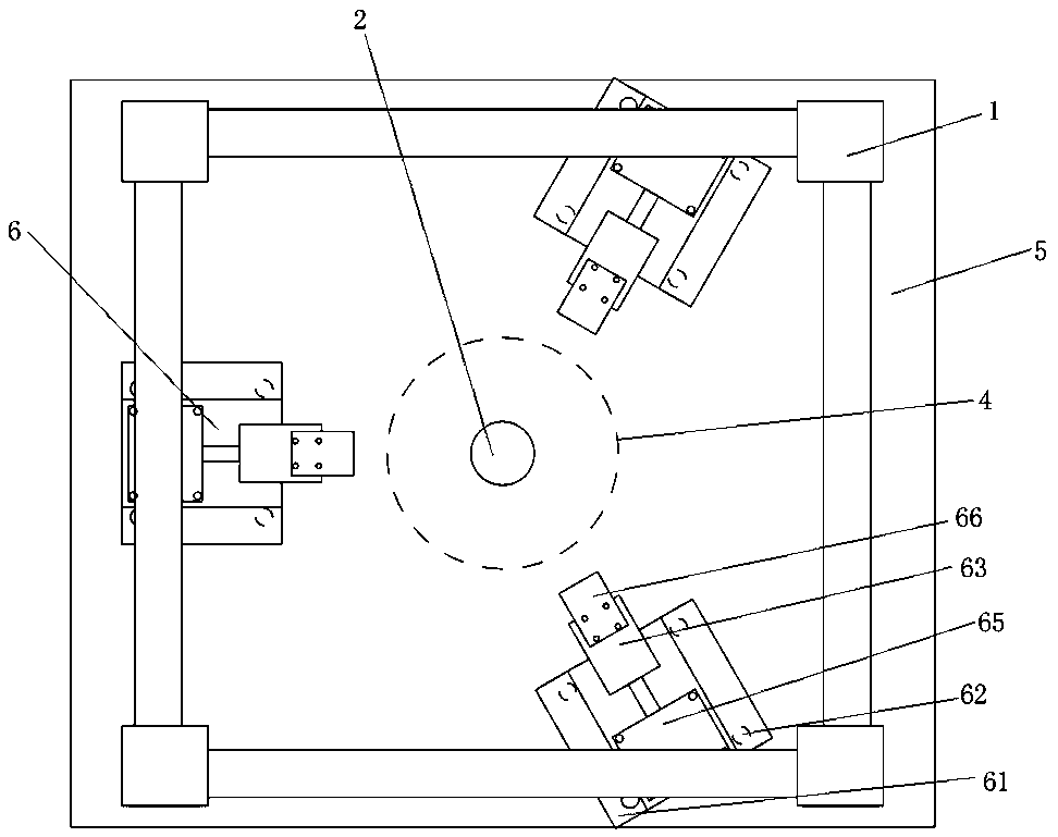
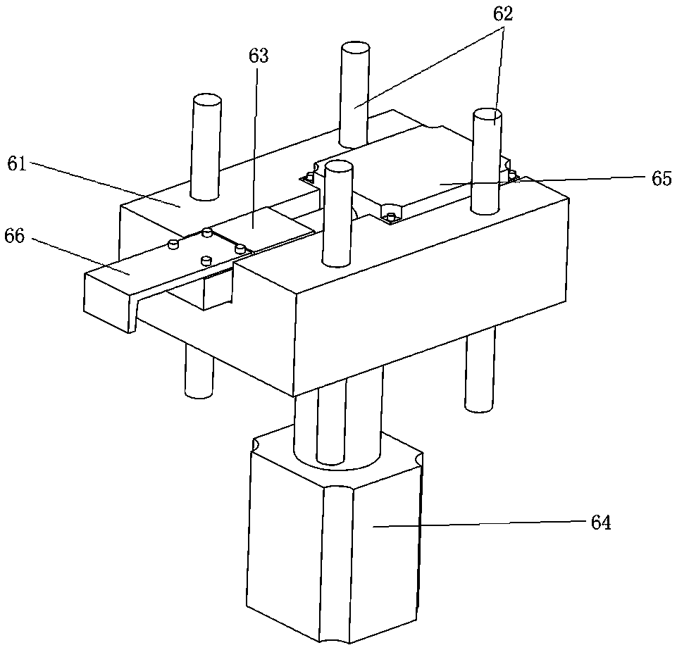
[0029] Such as figure 1 , 2 A wheel hub spinning machine shown in .3 includes a frame 1 in the form of a rectangular frame, a spindle module, and a spinning module 6. The spindle module includes the first vertically arranged upper and lower frame 1 for installing the wheel hub blank 4. A shaft group 2 and a second shaft group 3, the first shaft group 2 is longitudinally adjustable on the top plate of the frame 1, including a first servo motor 21 screwed to the top plate, connected to the output end of the first servo motor 21 And pass through the first shaft 22 extending downward from the top plate; the lower part of the frame 1 is equipped with a horizontally movable lower platform 7, and the second shaft group 3 is fixed on the lower platform 7, including screwed on the base plate 73 of the lower platform 7 The second servo motor 31 and the second shaft 32 connected to the...


PUM


Abstract

The invention relates to a wheel hub spinning machine, and relates to the field of wheel hub production equipment. The wheel hub spinning machine comprises a rack, a spindle module and spinning modules. The spindle module comprises a first shaft group and a second shaft group which are arranged on the rack in the longitudinal direction and used for mounting a wheel hub blank, the first shaft group, the second shaft group and the wheel hub blank are coaxial, a horizontal spinning platform is arranged in the middle of the rack, and the three spinning modules are circumferentially distributed around the wheel hub blank axis; and each spinning module comprises a base, a guide rail, a knife rest, a longitudinal hydraulic cylinder and a transverse hydraulic cylinder, wherein the guide rail is vertically arranged above the spinning platform, the base is movably mounted on the guide rail, the knife rest is movably arranged on the base and points to the wheel hub blank, and the longitudinal hydraulic cylinder is longitudinally connected to the base, and the transverse hydraulic cylinder is fixedly connected to the base and connected to the knife rest. Through the wheel hub spinning machine,the upper and lower ends of the wheel hub blank can be synchronously rotated to prevent deformation, diversified processes adapt to different production requirements, meanwhile, the good processing stability is achieved, and the production quality is improved.

Description

technical field [0001] The invention relates to the field of hub production equipment, in particular to a hub spinning machine. Background technique [0002] At present, the spinning technology is generally used for the cylindrical molding of the wheel hub. On the one hand, compared with the traditional casting molding, there will be no common problems in the traditional casting process such as sand holes, shrinkage cavities, and cracks, which can save raw materials and improve the qualified rate of finished products. ; On the other hand, the mechanical structure of the hub is more dense and the strength is higher. [0003] As described in the Chinese invention patent with the publication number CN204867001U, a welding-free automobile wheel hub spinning forming device includes an upper template, upper guide plates arranged on the left and right sides of the upper template, and a lower template arranged below the upper template, And the lower guide plates arranged on the lef...

Claims


Application Information

Patent Timeline
Patent Type & Authority Applications(China)
IPC IPC(8): B21D22/18B21D53/26
CPCB21D22/18B21D53/265
Inventor 骆耀斌
Owner ANHUI STRONG AUTO PARTS
Learn More