Punching machine

A punching machine and punching technology, applied in the direction of punching tools, metal processing equipment, manufacturing tools, etc., can solve the problems of bumper bumper punching processing and the position of the punching mechanism can not be adjusted, etc., to improve product quality , Improve flexibility, expand the effect of application range

Inactive Publication Date: 2019-01-15
ZHEJIANG LIMIN INDAL
View PDF12 Cites 2 Cited by
  • Summary
  • Abstract
  • Description
  • Claims
  • Application Information

AI Technical Summary

Problems solved by technology

[0004] Although the above-mentioned punching machine can complete multiple punching tasks through one punching operation, the positions of each punching mechanism cannot be adjusted, and the above-mentioned pun

Method used


Image

  • Punching machine
  • Punching machine
  • Punching machine

Examples


Embodiment 1

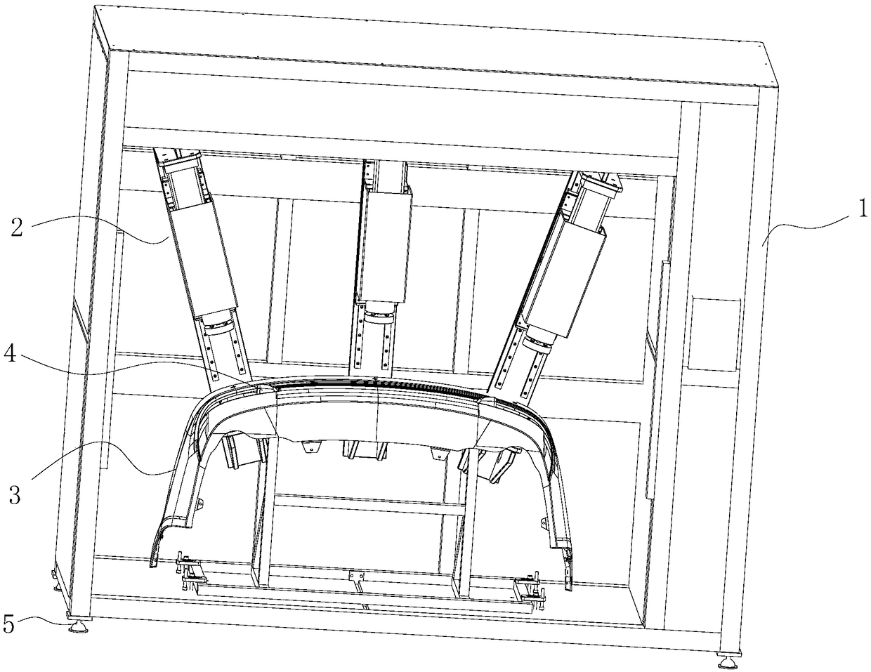
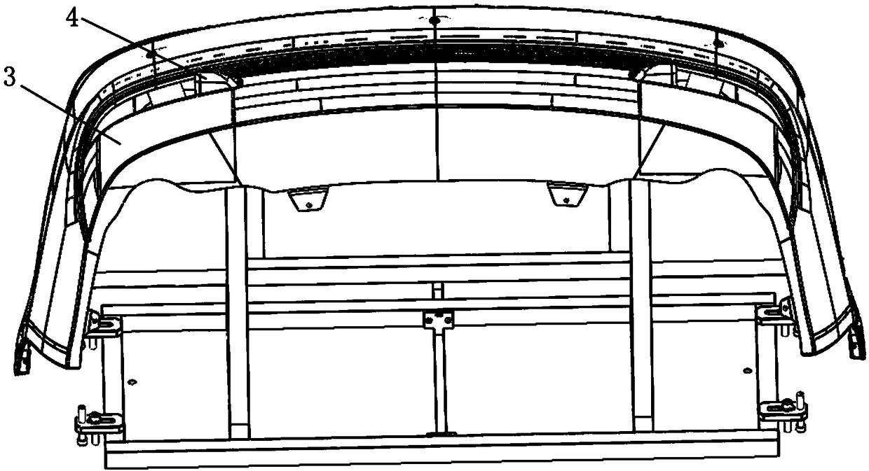
[0043] Such as Figure 1 to Figure 4 As shown, a punching machine is used for punching a workpiece 3 with a bent surface.

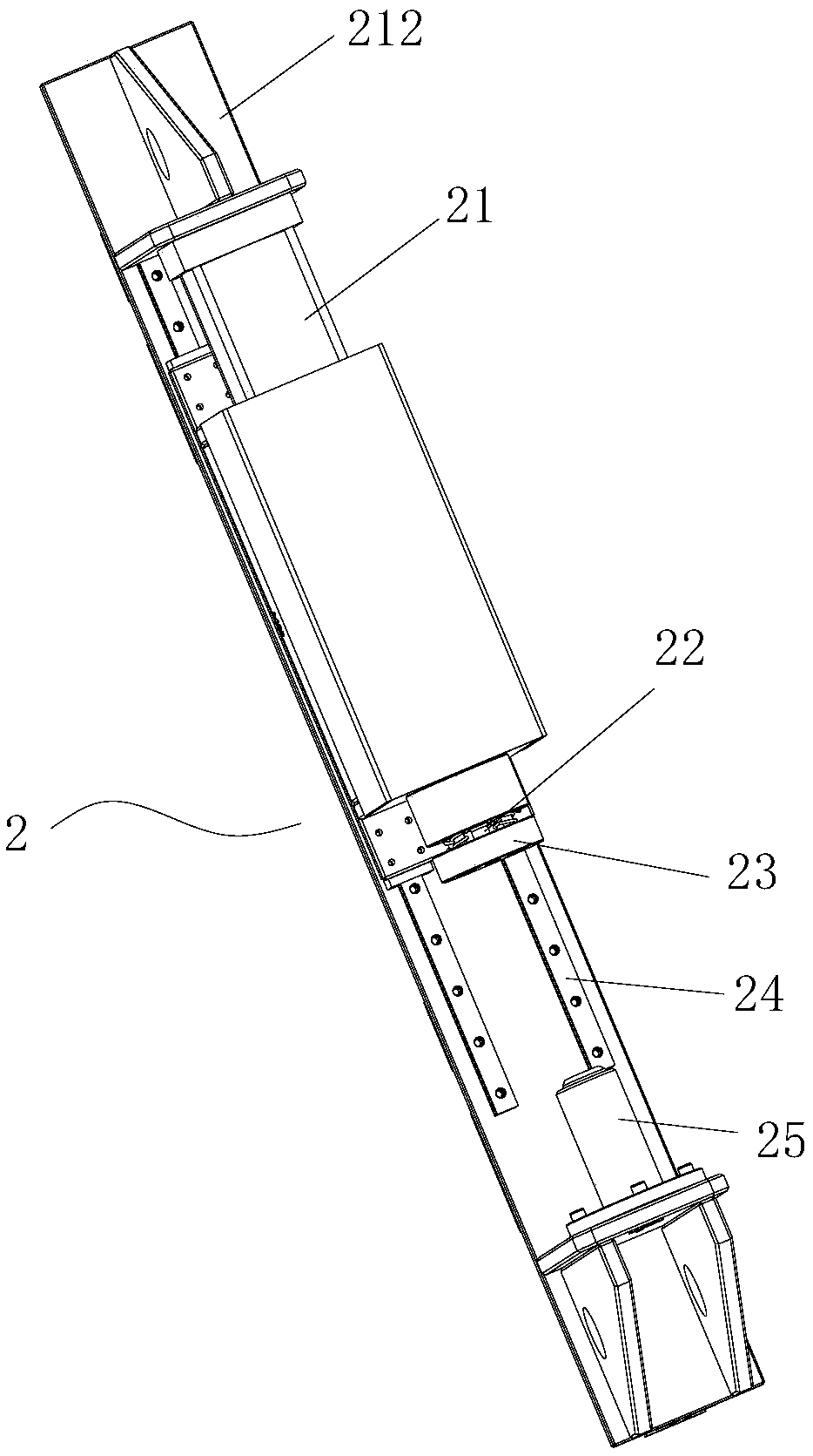
[0044] The punching machine includes a punching device, and the punching device includes a plurality of punching mechanisms 2 positioned above the workpiece. The plurality of punching mechanisms 2 are arranged at an angle along the contour of the workpiece 3, each The punching mechanism 2 includes a punch 22 .

[0045] The punching mechanism 2 further includes a mounting frame 212 and a first driving part 21 for driving the punch 22 to move, and the first driving part 21 is arranged on the mounting frame 212 . In this embodiment, the first driving part 21 is a hydraulic cylinder or an air cylinder. One end of the piston rod of the hydraulic cylinder or air cylinder is connected with the punch 22 through a connecting piece.

[0046] In order to meet the punching processing requirements of different apertures, in this application, the punch 22 is detachabl...

Embodiment 2

[0062] The structure and principle of this embodiment and embodiment 1 are basically the same, the difference is:

[0063] Different from the workpieces with different punching positions in Embodiment 1, it is necessary to change the installation position of the punching mechanism on the frame 1 to realize the relative positional relationship between the punch 22 and the punching position of the workpiece change. In this embodiment, the installation position of the punching mechanism 2 remains unchanged, but its installation angle can be changed. By changing its installation angle on the frame 1, the distance between its punch 22 and the punching position can be realized. Adjustment.

[0064] In this embodiment, each punching mechanism 2 is installed on the frame through at least one installation component. The installation assembly includes a fastener and a rotating part. The punching mechanism 2 can rotate around the rotating part. When the punching mechanism rotates until...

Embodiment 3

[0066] The structure and principle of this embodiment and embodiment 1 are basically the same, the difference is:

[0067] Different from the workpieces with different punching positions in Embodiment 1, several installation stations need to be set according to the positions to be punched of commonly processed workpieces, so as to change the installation position of the punching mechanism. In this embodiment, the adjustment of the installation position of the punching mechanism is realized through the following installation slots.

[0068] Such as Figure 5 to Figure 7 As shown, in this embodiment, the frame 1 is provided with a mounting groove for mounting the punching mechanism 2, and the extending direction of the mounting groove is at least consistent with the outline of a part of the workpiece 3, That is to say, the installation groove can be a straight guide chute, or a guide chute with a curved portion as the outline of the workpiece 3 . In this embodiment, the punchi...


PUM


Abstract

The invention discloses a punching machine. The punching machine is used for punching a workpiece with a bent surface. The punching machine comprises a punching device. The punching device comprises aplurality of punching mechanisms located above the workpiece. The plurality of punching mechanisms are arranged along the outline of the workpiece in an angle mode. Each punching mechanism comprisesa punch and a rack used for installing each punching mechanism. At least one punch can be used for adjusting the punching position of the workpiece, and the adjusting mode is used for changing the installation positions of the punching mechanisms on a machine frame and/or adjusting or adjusting the inclination angles of the punching mechanisms relative to the horizontal direction. The punching positions of the punching mechanisms can be adjusted according to the punching position requirements of to-be-machined workpieces. As a result, the machining requirements for different punching positionsof different products are met, and the application range of the punching machine is expanded.

Description

technical field [0001] The application belongs to the technical field of punching equipment, and in particular relates to a punching machine. Background technique [0002] Automobile bumper drilling is one of the automobile processing techniques. The early automobile bumper drilling was a simple impact drilling driven by manpower. With continuous evolution and development, various impact drills with mobile power drive appeared. Hole machine and impact puncher, but this kind of punching equipment has the problem of low efficiency. [0003] Patent CN206733161U discloses a punching machine, which is used for punching automobile bumpers. The punching machine includes: a frame, which is covered by a casing; a punching device, which includes several punching mechanisms, several The punching mechanism is located above the automobile bumper, and is arranged according to the shape of the automobile bumper; the fixing device includes a pre-pressing mechanism and a supporting mechanis...

Claims


Application Information

Patent Timeline
IPC IPC(8): B21D28/34B21D53/88
Inventor 颜建民黄财耘管康宾徐从洲
Owner ZHEJIANG LIMIN INDAL
Why Eureka
Try Eureka