Gear rack transmission mechanism for cutting machine saw plate and cutting machine

A technology of rack and pinion and transmission mechanism, applied in the attachment of sawing machines, metal sawing equipment, metal processing and other directions, can solve the problems of low transmission efficiency, short service life, high failure rate, and achieve safe and reliable work and service life. The effect of long and low failure rate

Pending Publication Date: 2019-01-15
广东海富纳数控科技有限公司
View PDF0 Cites 0 Cited by
  • Summary
  • Abstract
  • Description
  • Claims
  • Application Information

AI Technical Summary

Problems solved by technology

[0003] The purpose of this application is to provide a rack and pinion transmission mechanism and cutting machine for cutting machine saw discs, so as to solve the technical problems of low transmission efficiency, high failure rate and short service life in the prior art

Method used


Image

  • Gear rack transmission mechanism for cutting machine saw plate and cutting machine
  • Gear rack transmission mechanism for cutting machine saw plate and cutting machine
  • Gear rack transmission mechanism for cutting machine saw plate and cutting machine

Examples


Embodiment Construction

[0029] The technical solutions of the present invention will be clearly and completely described below in conjunction with the accompanying drawings. Apparently, the described embodiments are some of the embodiments of the present invention, but not all of them.

[0030] The components of the embodiments of the invention generally described and shown in the figures herein may be arranged and designed in a variety of different configurations. Accordingly, the following detailed description of the embodiments of the invention provided in the accompanying drawings is not intended to limit the scope of the claimed invention, but merely represents selected embodiments of the invention.

[0031] Based on the embodiments of the present invention, all other embodiments obtained by persons of ordinary skill in the art without making creative efforts belong to the protection scope of the present invention.

[0032] In the description of the present invention, it should be noted that the...


PUM

PropertyMeasurementUnit
Arc angleaaaaaaaaaa

Abstract

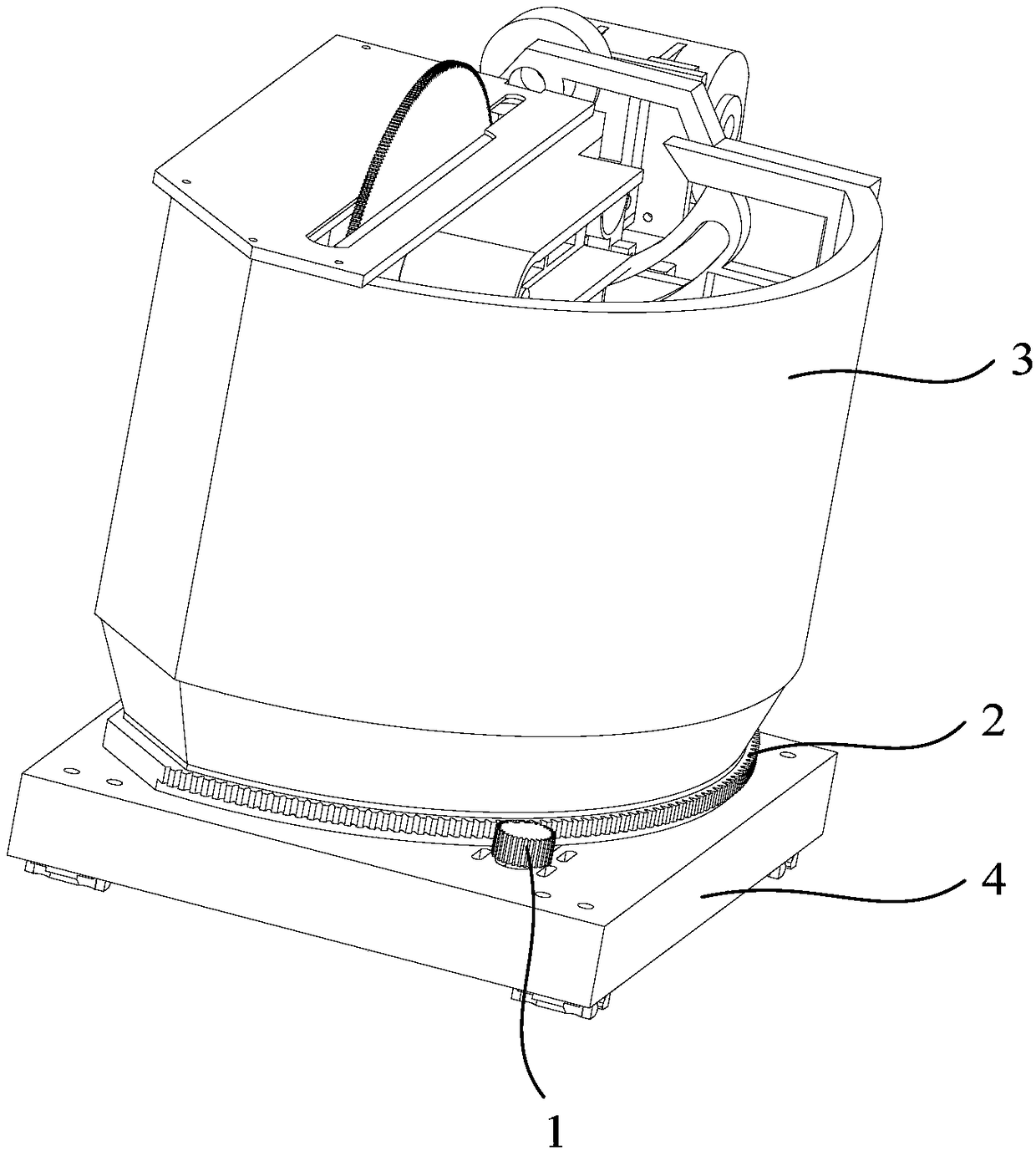
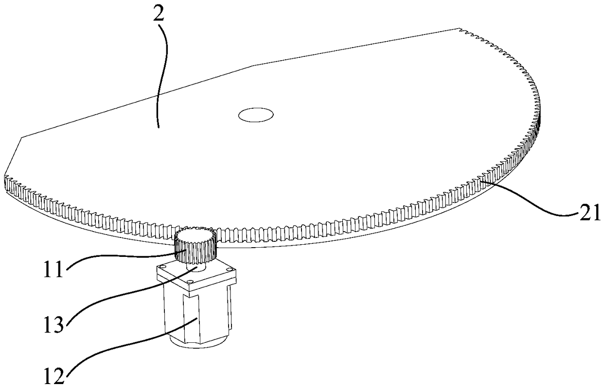
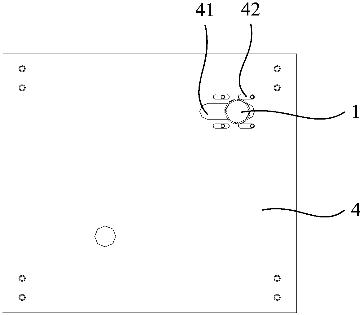
The invention relates to the field of mechanical equipment, in particular to a gear rack transmission mechanism for a cutting machine saw plate and a cutting machine. The gear rack transmission mechanism for the cutting saw plate comprises a gear driving assembly, a rack bottom plate, a machine head and a frame bottom plate, wherein the machine head is fixedly arranged on the rack bottom plate; the rack bottom plate is positioned on the frame bottom plate; the rack bottom plate and the frame bottom plate are connected through a revolving shaft; the gear driving assembly comprises a gear; the gear is meshed with a rack. When the gear rotates, the rack bottom plate rotates around the revolving shaft, and drives the machine head which is fixedly arranged on the rack bottom plate and the saw plate in the machine head to rotate at the same time. Thus, through gear rack transmission with high transmission efficiency and low fault rate, the aim of driving the saw plate to rotate is fulfilled,the service life of the cutting machine is prolonged, and working is safer and more reliable.

Description

technical field [0001] The invention relates to the field of mechanical equipment, in particular to a rack and pinion transmission mechanism of a saw disc of a cutting machine and a cutting machine. Background technique [0002] The saw disc transmission of the existing cutting machine mainly relies on the belt drive to rotate the machine head, thereby driving the saw disc to rotate, but the transmission efficiency of the belt drive is low, and the belt is easy to wear and has a high failure rate. Contents of the invention [0003] The purpose of the present application is to provide a rack and pinion transmission mechanism for the saw disc of a cutting machine and a cutting machine to solve the technical problems of low transmission efficiency, high failure rate and short service life in the prior art. [0004] The present application provides a rack and pinion transmission mechanism of a cutting machine saw disc, including a gear drive assembly, a rack bottom plate, a ma...

Claims


Application Information

Patent Timeline
IPC IPC(8): B23D59/00B23Q5/00
CPCB23D59/00B23Q5/00
Inventor 李海田
Owner 广东海富纳数控科技有限公司
Why Eureka
Try Eureka