Nail removing device

A technology of roller shaft and chassis, applied in the direction of nail pullers, manufacturing tools, etc., can solve the problems of high labor intensity and low efficiency, and achieve the effect of simple structure

Inactive Publication Date: 2019-01-15
刘成其
View PDF0 Cites 1 Cited by
  • Summary
  • Abstract
  • Description
  • Claims
  • Application Information

AI Technical Summary

Problems solved by technology

[0003] In order to solve the problem of manual use of pliers or claw hammer to remove discarded nails, the labor inten...

Method used


Image

  • Nail removing device

Examples


Embodiment Construction

[0009] The present invention will be further described below in conjunction with the accompanying drawings and embodiments.

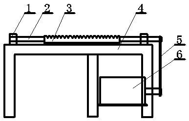
[0010] As shown in the figure, a horizontal roller shaft 2 is installed on a cuboid chassis 4, and an axial rack 3 is installed on the roller shaft 2. The two ends of the roller shaft 2 are connected with the chassis 4 by the shaft seat 1. The bottom of the gear box is equipped with a speed reducer 6, and a transmission belt 5 is housed between the speed reducer 6 and the roller shaft 2.

[0011] During work, first start the reducer 6 to drive the roller shaft 2 and the rack 3 to rotate, then insert the nails on the wooden parts into the tooth spaces of the rack 3 and hold the wooden parts, the nails will be pulled out by the rotating rack 3 out.


PUM


Abstract

A nail removing device is characterized in that a transverse roller shaft is mounted on a cuboid-shaped bottom frame, wherein an axial rack is mounted on the roller shaft; two ends of the roller shaftare connected to the bottom frame through a shaft seat; a speed reducer is mounted at the lower part of the bottom frame; and a transmission belt is mounted between the speed reducer and the roller shaft. The device solves the problems of high working intensity and low efficiency in the operation of manually removing wasted nails through tongs or a claw hammer; and the device is widely applied toprocessing of carpentry.

Description

technical field [0001] The invention relates to the field of wood processing machinery, in particular to a machine for pulling out nails on wooden workpieces. Background technique [0002] At present, people use pliers or claw hammers to remove discarded nails during the woodworking process. The disadvantage is that the labor intensity is high and the efficiency is low. Contents of the invention [0003] The invention provides a machine for pulling out nails with a rack structure in order to solve the problems of high labor intensity and low efficiency for manually removing discarded nails with pliers or a claw hammer. [0004] The technical solution of the present invention is a nail removal device, which is special in that a horizontal roller shaft is installed on a cuboid chassis, an axial rack is installed on the roller shaft, and the two ends of the roller shaft are formed by shaft seats and The bottom frame is connected, and the lower part of the bottom frame is equ...

Claims


Application Information

Patent Timeline
IPC IPC(8): B25C11/00
CPCB25C11/00
Inventor 刘成其
Owner 刘成其
Why Eureka
Try Eureka