A large-span mobile device for positioning the rear spar of an aircraft wing and a method of using the same

A technology for rear beam and aircraft, which is applied in the aerospace field, can solve the problems of regular maintenance of pallets, narrow assembly space, collision, etc., and achieve the effect of improving positioning accuracy, improving assembly efficiency, and improving assembly quality.

Inactive Publication Date: 2019-01-15
AVIC BEIJING AERONAUTICAL MFG TECH RES INST
View PDF7 Cites 2 Cited by
  • Summary
  • Abstract
  • Description
  • Claims
  • Application Information

AI Technical Summary

Problems solved by technology

[0004] The existing technology of tooling positioning and manual assembly methods is insufficient. 1. Use the supporting beam on the overturned pallet to locate the rear beam. The positioning of the rear beam is not accurate

Method used


Image

  • A large-span mobile device for positioning the rear spar of an aircraft wing and a method of using the same
  • A large-span mobile device for positioning the rear spar of an aircraft wing and a method of using the same
  • A large-span mobile device for positioning the rear spar of an aircraft wing and a method of using the same

Examples


Embodiment Construction

[0043] In order to make the technical solutions and advantages in the embodiments of the present application clearer, the exemplary embodiments of the present application will be further described in detail below in conjunction with the accompanying drawings. Apparently, the described embodiments are only part of the embodiments of the present application, and Not an exhaustive list of all embodiments. It should be noted that, in the case of no conflict, the embodiments in the present application and the features in the embodiments can be combined with each other.

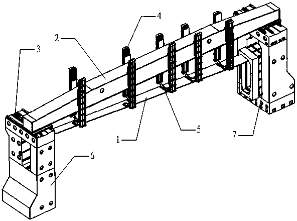
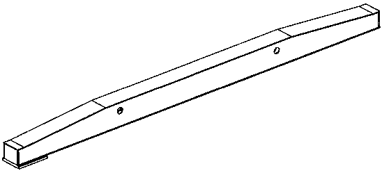
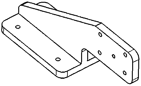
[0044] Such as figure 1 As shown, this embodiment proposes a large-span mobile device for positioning the rear beam of an aircraft wing, which includes: a mobile beam 2, a beam drive assembly 3, a rear beam joint positioner 4, a process joint 5, and a left gantry column assembly 6 and the right gantry column assembly 7;

[0045] The bottoms of the left and right ends of the moving beam 2 are respectively fixed wi...


PUM


Abstract

The invention provides a large-span mobile device for positioning the rear spar of an aircraft wing, which relates to the technical field of aerospace. The device comprises a moving crossbeam, crossbeam driving assemblies, a rear beam joint positioner, a process joint, a left gantry column assembly and a right gantry column assembly. The crossbeam driving assemblies are fixed at the bottom of theleft and right end of the moving crossbeam, wherein a left gantry column assembly is fixed at the bottom of one of the cross beam driving assemblies, a right gantry column assembly is fixed at the bottom of the other cross beam drive assembly, the crossbeam driving assembly drives the moving crossbeam to perform linear motion perpendicular to the longitudinal direction of the moving crossbeam on the left gantry column assembly and the right gantry column assembly, A rear beam joint positioner is arranged on the side wall of the moving cross beam, and the rear beam joint positioner is cooperatively connected with a process joint arranged on the rear beam for assembling and positioning the rear beam. A method for using the device as described above is also provided. The invention improves the positioning accuracy of the rear beam.

Description

technical field [0001] This application relates to the field of aerospace technology, in particular to a large-span mobile device for positioning the rear beam of an aircraft wing and its application method Background technique [0002] At present, in the wing assembly process of aircraft factories at home and abroad, fixed type frames and pallet positioning are mainly used to support the rear beam of the wing of the aircraft to ensure the position of the rear beam of the wing, and traditional tooling positioning and manual assembly methods are used. Since the 1990s, aircraft manufacturers represented by Boeing and Airbus have adopted digital and automated technologies to digitalize and automate the assembly of the wings of Boeing 787, A400M and other aircraft. [0003] The rear beam of the wing is about 10m long, 0.5m wide, and 0.1m thick. The upper and lower wallboard flip clamps are designed on the frame, and the top of the lower wall board flip clamps is designed with a...

Claims


Application Information

Patent Timeline
IPC IPC(8): B64F5/10
CPCB64F5/10
Inventor 荆道艳陈龙袁伟秦玉波申望
Owner AVIC BEIJING AERONAUTICAL MFG TECH RES INST
Why Eureka
Try Eureka