A large displacement seamless composite expansion joint and a bridge
A large displacement, expansion joint technology, applied in bridges, bridge parts, bridge construction and other directions, can solve the problems of complex structure, easy entry of sand and gravel particles, affecting the use function, etc., to achieve reasonable structure, convenient and flexible construction and maintenance, and suitable for wide range of effects
- Summary
- Abstract
- Description
- Claims
- Application Information
AI Technical Summary
Problems solved by technology
Method used
Image
Examples
specific Embodiment approach 1
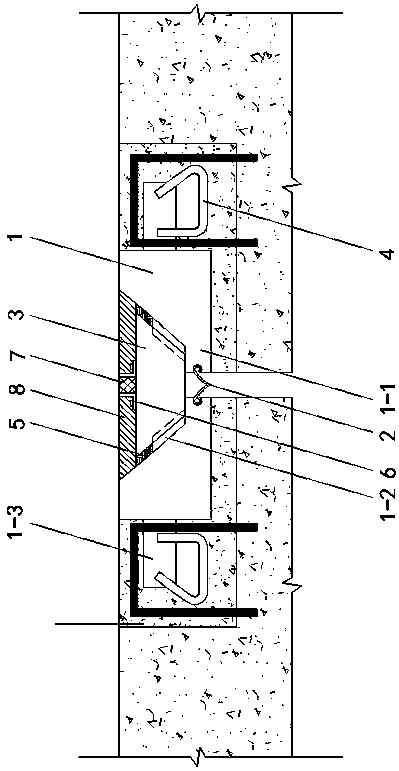
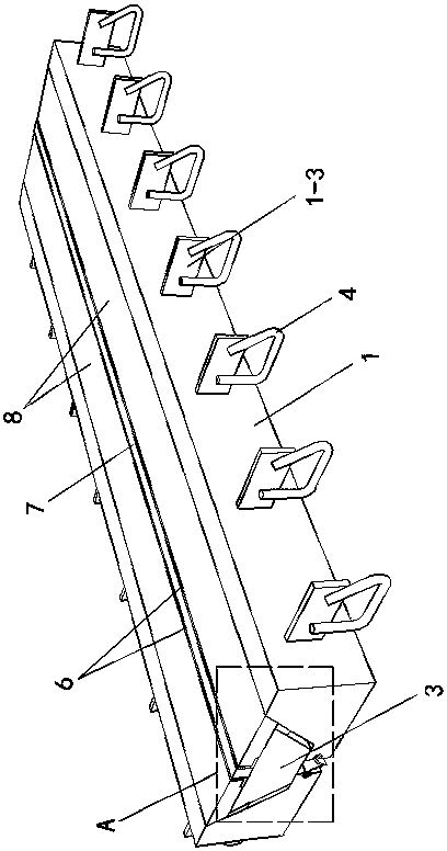
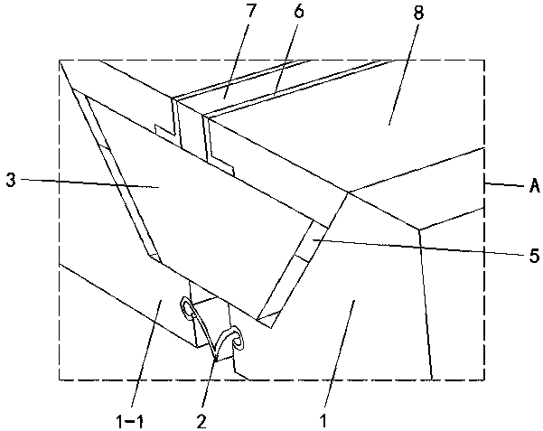
[0015] Specific implementation mode one: as Figure 1~Figure 5 As shown, the present invention discloses a large-displacement seamless combined expansion joint, which includes a waterstop 2, an elastic filling belt 7, two joists 1, two pavement layers 8, and a plurality of precast concrete blocks 3. The cross-sections of the two joists 1 are right-angled trapezoidal, and the lower bottom of each joist 1 extends horizontally in the direction of the inclined surface with a protruding portion 1-1, and the protruding portions 1-1 of the two joists 1 The waterstops 2 are installed at intervals relative to each other, and the waterstop 2 is loosely installed between the two protruding parts 1-1. A row of combs is fixed at the angle between the inclined surface of each joist 1 and the protruding part 1-1 along its length direction. board 1-2, the shape of the comb board 1-2 is parallelogram and the direction is consistent with the direction of the protruding part 1-1, and the plurali...
specific Embodiment approach 2
[0016] Specific implementation mode two: as figure 1 , 2 , 4, this embodiment is a further description of specific embodiment one. The vertical surfaces of the two joists 1 are respectively fixed with a row of embedded steel plates 1-3 along the length direction, and the embedded steel plates 1-3 3 are all welded and fixed with connecting steel bars 4.
specific Embodiment approach 3
[0017] Specific implementation mode three: as figure 1 , 3 As shown, this embodiment is a further description of specific embodiment 1 or specific embodiment 2. The opposite end surfaces of the two protruding parts 1-1 are respectively provided with grooves, and the water stop belt 2 is tightly plugged. and be clamped between the two grooves.
PUM
 Abstract
Description
Claims
Application Information
 - R&D
- Intellectual Property
- Life Sciences
- Materials
- Tech Scout
- Unparalleled Data Quality
- Higher Quality Content
- 60% Fewer Hallucinations
Browse by: Latest US Patents, China's latest patents, Technical Efficacy Thesaurus, Application Domain, Technology Topic, Popular Technical Reports.
© 2025 PatSnap. All rights reserved.Legal|Privacy policy|Modern Slavery Act Transparency Statement|Sitemap|About US| Contact US: help@patsnap.com


