
Integral lifting construction method for cooling tower system and steel gallery

A technology of overall improvement and construction method, which is applied in the direction of construction, building structure, and building material processing, etc., and can solve problems affecting the installation and construction progress of electromechanical equipment, large construction difficulty and safety risks, and affecting the overall stability of the steel corridor structure, etc. , to achieve the effect of improving the quality and efficiency of installation and construction, reducing the difficulty of hoisting and assembling, and saving labor

Active Publication Date: 2019-01-15
CHINA CONSTR THIRD ENG BUREAU INSTALLATION ENG CO LTD
View PDF6 Cites 7 Cited by
  • Summary
  • Abstract
  • Description
  • Claims
  • Application Information

AI Technical Summary

Problems solved by technology

[0006] 3. The hoisting construction of the cooling tower needs to wait until the overall hoisting of the steel corridor structure is completed, and then the concrete is poured, which seriously affects the construction progress of the mechanical and electrical equipment installation;
[0007] 4. The cross construction of steel structures and equipment pipelines may affect the overall stability of the steel corridor structure, especially factors such as operating weight and noise resonance have a major impact;
[0008] 5. There are great construction difficulties and safety risks in the installation of cooling tower systems for high-altitude operations

Method used


Image

  • Integral lifting construction method for cooling tower system and steel gallery
  • Integral lifting construction method for cooling tower system and steel gallery
  • Integral lifting construction method for cooling tower system and steel gallery

Examples


Embodiment Construction

[0049]The following will clearly and completely describe the technical solutions in the embodiments of the present invention with reference to the accompanying drawings in the embodiments of the present invention. Obviously, the described embodiments are only some, not all, embodiments of the present invention. Based on the embodiments of the present invention, all other embodiments obtained by persons of ordinary skill in the art without making creative efforts belong to the protection scope of the present invention.

[0050] In describing the present invention, it is to be understood that the terms "center", "upper", "lower", "front", "rear", "left", "right", "vertical", "horizontal", The orientations or positional relationships indicated by "top", "bottom", "inner", "outer", etc. are based on the orientations or positional relationships shown in the drawings, and are only for the convenience of describing the present invention and simplifying the description, rather than ind...


PUM


Abstract

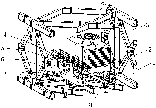
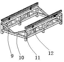
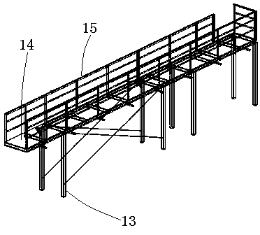
The invention provides an integral lifting construction method for a cooling tower system and a steel gallery, which comprises the steps of 1) conducting pre-construction preparation, firstly buildinga cooling tower steel structure supporting foundation model, a cooling tower maintenance platform model and a pipeline support model, then building an integral structure model by combining the builtmodels with a cooling tower, a cooling water pipeline and a steel gallery, performing stress simulation analysis on the model, ensuring the stress of each part in the lifting process to meet requirements, and deepening the design of construction drawings; 2) splicing the cooling tower system and the steel gallery on the ground according to the construction drawings; and 3) and integrally and synchronously lifting the spliced cooling tower system and steel gallery through a hydraulic lifting system. According to the invention, the cooling tower system and the steel gallery are firstly spliced on the ground and then integrally lifted, thereby reducing the hoisting and splicing difficulty of components of the cooling tower system, and saving the labor. In addition, the components of the cooling tower system can be simultaneously spliced, thereby ensuring the construction period, improving the installation and construction quality and efficiency of the cooling tower system.

Description

technical field [0001] The invention belongs to the technical field of building construction, and in particular relates to an integral lifting construction method of a cooling tower system and a steel corridor. Background technique [0002] At present, in order to reduce the potential safety hazards of the steel corridors in China, the method of reducing the weight of the steel corridors is generally adopted, only the frame of the steel corridors is assembled in place, and then the lifting is carried out. Boards, greening, equipment, etc. are all installed after the steel corridor is lifted and placed in place. [0003] The following construction problems exist when the cooling tower system is installed on the steel corridor by adopting the existing scheme of lifting the steel corridor first and then hoisting the equipment: [0004] 1. The cooling tower is large in size and heavy in weight. It also includes pipes and brackets. To hoist it to the installation height of the s...

Claims


Application Information

Patent Timeline
IPC IPC(8): E04G21/14
CPCE04G21/14
Inventor 裴以军赵广振李永峰孟亮申均卫刘凡梁杨
Owner CHINA CONSTR THIRD ENG BUREAU INSTALLATION ENG CO LTD
Learn More